Defining a Workplane
Define a workplane to assist with aligning the patch on the quadcopter.
-
Hide the patch antenna in the 3D view to focus on the
quadcopter.
-
In the model tree, click the icon next to
Union1.
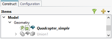
Figure 1. Union1 is greyed out to indicate that the part is hidden in the 3D view.
-
In the model tree, click the icon next to
Union1.
-
Hide the simulation mesh1 to focus on the geometry using one of the following workflows:
- On the status bar, click the
 Overlay icon.
 - On the 3D View
context tab, on the Display Options tab, in the
Display Mode group,
click the
Overlay icon.
- On the status bar, click the
-
Define a workplane.
-
On the Construct tab, in the Define group, click the
 Add Workplane icon.
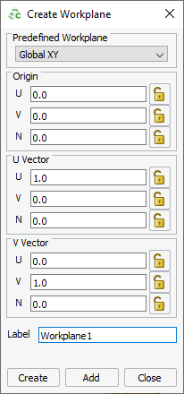
Figure 2. The Create Workplane dialog. -
Press Ctrl+Shift while moving the
mouse cursor over the top face centre of the quadcopter.
Note: The circles with a black outline indicate special snapping points. The red outline indicates the position of the mouse cursor.
Use snapping points to snap the workplane to an object. Although only special snapping points are indicated, you can snap to any point in the 3D view.
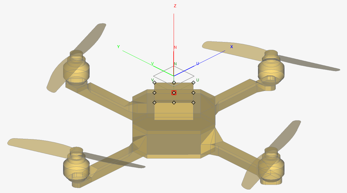
Figure 3. Special snapping points are indicated by circles with a black outline. The red outline indicates the position of the mouse cursor. -
Click Create to create
Workplane1 and to close the dialog.

Figure 4. Workplane1 has snapped to the top centre of the quadcopter.
-
On the Construct tab, in the Define group, click the
-
Align Workplane1 with the top of the quadcopter.
-
On the Rotate dialog, under Rotation
angle, in the Angle [degrees]
field, specify a value of 45°.
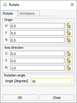
Figure 5. The Rotate dialog. -
Click OK to rotate Workplane1
and to close the dialog.
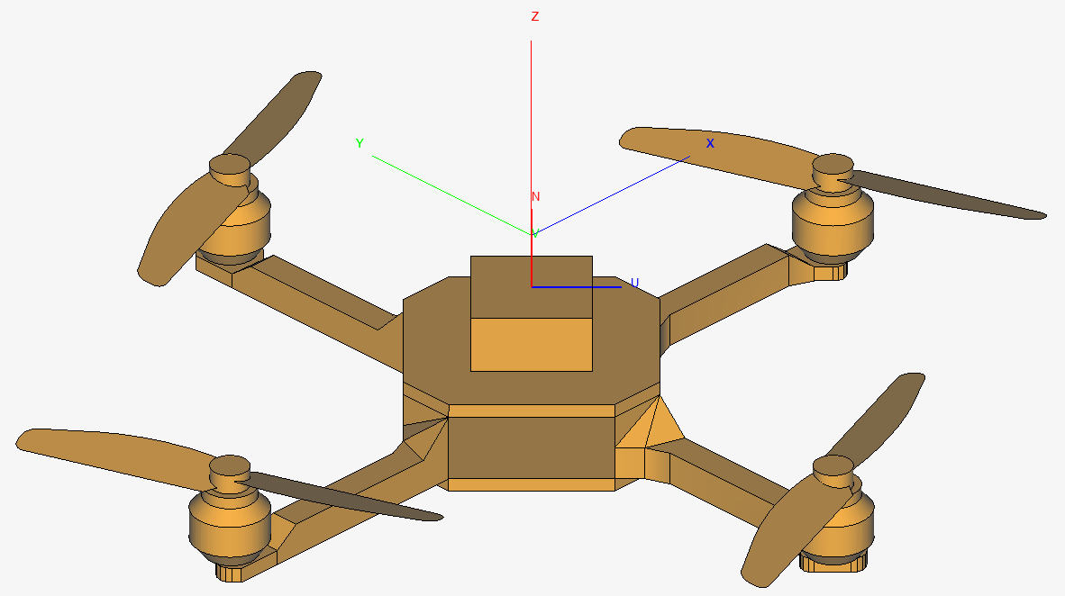
Figure 6. Workplane1 is “aligned” to the top centre of the quadcopter.
-
On the Rotate dialog, under Rotation
angle, in the Angle [degrees]
field, specify a value of 45°.
- Repeat Step 1 to show the patch again.
1 The simulation mesh refers to the final mesh used by the
Solver. CAD always has to be meshed.