Creating the Bent Dipole
Create the bent dipole using a polyline.
To illustrate the usage of custom workplanes, the bent dipole is created using a
custom workplane.
-
On the Construct tab, in the Create Curve group, click the
 Polyline icon.
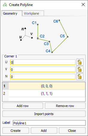
Figure 1. The Create Polyline dialog showing the default values. Active fields are outlined in yellow.Note: Default values are used on geometry creation dialogs to allow a preview in the 3D view. You may change the values as required.Tip: An active field allowing point-entry is indicated by a yellow outline.Point-entry allows a variable or named points to be entered by pressing Ctrl+Shift+left click on a variable or named point in the model tree.
Figure 2. The bent dipole with corner point on the X axis.