Creating the Patch

Create the chamfered1 patch using a polygon.

  1. On the Construct tab, in the Create Surface group, click the  Polygon icon.


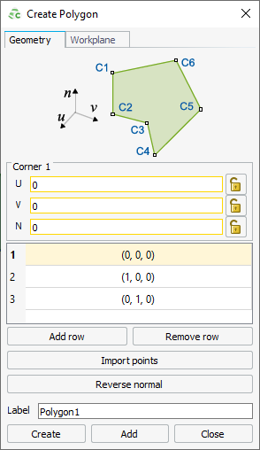
    Figure 1. The Create Polygon dialog showing the default values. Active fields are outlined in yellow.
    Note: Default values are used on geometry creation dialogs to allow a preview in the 3D view. You may change the values as required.
    Tip: An active field allowing point-entry is indicated by a yellow outline.

    Point-entry allows a variable or named points to be entered by pressing Ctrl+Shift+left click on a variable or named point in the model tree.

  2. Under Corner 1, add the following coordinates:
    • Corner 1:
      • U: patch_size
      • V: patch_size
      • N: substrate_h
  3. In the table, click on the second row to make Corner 2 active. Add the following coordinates:
    • Corner 2:
      • U: -patch_size + chamfer_d
      • V: patch_size
      • N: substrate_h
  4. Click on the third row to make Corner 3 active. Add the following coordinates:
    • Corner 3:
      • U: -patch_size
      • V: patch_size - chamfer_d
      • N: substrate_h
  5. Click Add row for Corner 4. Add the following coordinates:
    • Corner 4:
      • U: -patch_size
      • V: -patch_size
      • N: substrate_h
  6. Repeat Step 5 twice to add Corner 5 and Corner 6 using the following coordinates:
    • Corner 5:
      • U: patch_size - chamfer_d
      • V: -patch_size
      • N: substrate_h
    • Corner 6:
      • U: patch_size
      • V: -patch_size + chamfer_d
      • N: substrate_h
  7. Set the Label to patch.


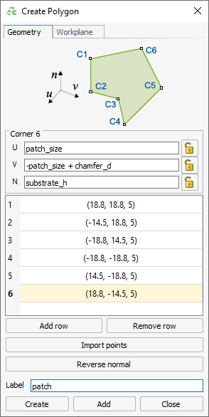
    Figure 2. The Create Polygon dialog.
  8. Click Create to create the polygon and to close the dialog.


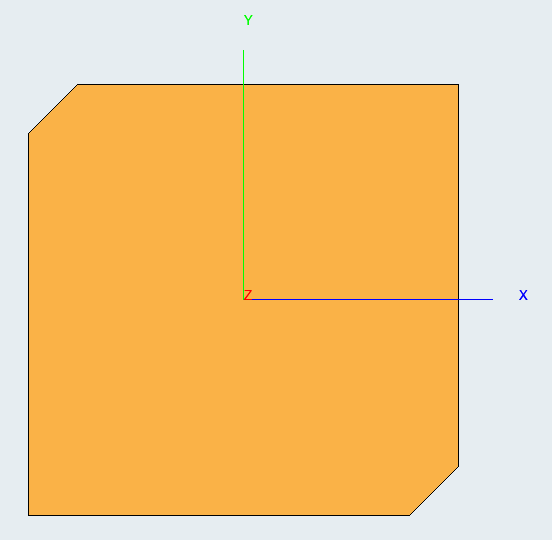
Figure 3. Top view of the chamfered patch. Note that the face is set to perfect electric conductor (PEC) by default (PEC is indicated by the colour orange).
1 An edge created at 45° between two adjoining right-angled edges.