Creating a Cylindrical / Circular Antenna Array
Create a cylindrical or circular finite antenna array model.
-
On the Construct tab, in the Structures
group, click the
 Planes/Arrays icon. From the drop-down list, select the
  Cylindrical/Circular Array icon.
-
In the Label field, add a unique label for the antenna
array.
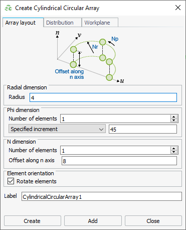
Figure 1. The Create Cylindrical Circular Array dialog. -
Click the Distribution tab to specify the array
distribution.
- To create an antenna array where the distribution is calculated from the plane wave (if a plane wave is present in the model), click the Uniform distribution or calculated from plane wave check box.
- To create an antenna array with a specified excitation for each element,
clear the Uniform distribution or calculated from plane
wave check box.Note: When specifying each element, take note of the array element indexing.

Figure 2. Image depicting the array element indexing.- To specify the magnitude scaling and phase offset manually:
- In the Magnitude scaling field, specify the excitation magnitude for the individual element relative to the base element.
- In the Phase offset (degrees) field, specify the phase offset (in degrees) for the individual element relative to the base element.
- To specify the magnitude scaling and phase offset by importing the
points from file, click Import.
- In the File name field, browse for the file you want to import.
- [Optional] In the Scale by field, enter a value to scale the points.
- Under Delimiter, click the delimiter type you use in your file.
- Click OK to close the Import Points dialog.
- To specify the magnitude scaling and phase offset manually: