Use advanced settings to specify the sampling point density, mesh refinement close to
cable terminals and the cable cross section orientation along the cable path.
On the Cables tab, in the
Definitions group, click the Cable Path icon.
The advanced settings are available on the Advanced tab.
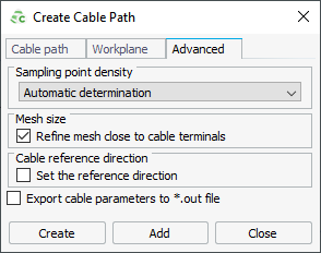
Figure 1. The Create Cable Path dialog
(Advanced tab).
Sampling Point Density
Each cable path is subdivided into segments to compute the induced currents and
voltages. At the centroid of each segment, the electric field strength and magnetic
field strength are evaluated. You can specify the segment length to influence the
accuracy of the computed results.
Automatic determination
This option allows CADFEKO to determine the
segment lengths.
Specify maximum separation distance
This option allows you to specify the segment lengths.
Mesh Size
Refine mesh close to cable terminals
This option enables automatic mesh refinement near cable terminals.
Cable Reference Direction
Select the Cable reference direction check box to manually
orientate the cable cross section along a cable path. Enter the following fields to
change the orientation.
U, V and N
Specify the U coordinate, V coordinate and N coordinate at the start of the cable path for
the cable reference direction.
Twist angle
Enter the angle at the cable path end to twist the cable cross section along
the path (in degrees).
Note:
The Cable reference direction may not be parallel to the
first cable path segment.
Export Cable Parameters
Export cable parameters to *.out file
This option exports the cable parameters such as inductance/capacitance
matrices and transfer impedance/admittance to the
.out file.
 Cable Path icon.
The advanced settings are available on the Advanced tab.
Cable Path icon.
The advanced settings are available on the Advanced tab.