Coupling Interface Programming Guide
Introduction
This programming guide provides an overview of how to use the EDEM Coupling Interface to couple with a generic CFD code and/or multibody dynamics codes. Programming implementation information for the interface is also provided and can be found in the EDEM Coupling Interface class, IEDEMCoupling.h.
The EDEM Coupling Interface enables users to construct coupled fluid - particle simulations between CFD codes and EDEM, coupled simulation between rigid/ multi body dynamics codes and EDEM or couple EDEM to programs written by the user. The Coupling Interface enables two independent programs to operate synchronously, sharing data to create a single ‘coupled’ simulation.
The EDEM Coupling Interface adopts TCP/IP client – server architecture which uses messages for communication between the two separate programs. Users may implement a new coupling with a physics code, using C++, to program a solution utilizing the EDEM Coupling Interface.
Note: When writing programs using the EDEM Coupling Interface all units are SI.
Communication between EDEM and a physics code using the EDEM Coupling Interface:

Coupling Simulation Sequence
During a coupled EDEM simulation, EDEM and the coupled 3rd party code simulate, in an alternating manner, with the 3rd party code first. The 3rd party code will simulate ahead in time and then pass any required data across to EDEM for it to be allowed to simulate to the same point in time. This alternating pattern continues until the simulation time has reached the specified end time, shown in the image below. Due to the explicit time integration methods implemented in EDEM, it is common that multiple time steps are required to simulate the same time period as a single time step of either a CFD or multibody dynamics simulation. Therefore time steps between the two solvers are potentially different, however the simulation-steps are the same.
The alternating sequence of a coupled simulation:

Each time the EDEM Coupling Interface sends a message to EDEM it blocks any further messages from being sent until EDEM returns a response. This synchronous behavior effectively pauses the 3rd party code until EDEM has calculated the required simulation step.
EDEM Coupling Interface Packaging
The EDEM Coupling Interface comprises client and server components. The server component resides within EDEM and the client component is to be used by the 3rd party code to interact with EDEM. The EDEM Coupling Client interface class provides users with a number of methods for setup, simulation and data control.
Overview of the packaging of the EDEM Coupling Interface:
Enabling and Running the Coupling Server
The EDEM Coupling Server options are accessible on the top right corner of your EDEM window.
Coupling server:
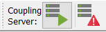
The left icon starts or stops the coupling server. The right icon provides the current status of the coupling: “Disabled”, “Awaiting incoming Connection” or “Connected”.
Starting and stopping the server:
Note: By default EDEM will launch with the Coupling Server stopped and requires the user to press the “Start” button before a coupled simulation can proceed. For running in batch mode or for making the process more automated EDEM can be launched with the Coupling Server already running by adding the ‘--cs’ switch to the command line.
Coupled EDEM-CFD Simulation Overview
EDEM integrates fluid drag forces and torques into the particle simulation on an individual particle level. When EDEM performs a step of the simulation the external forces act upon the particles in addition to any gravitational or collision forces. The stages of the EDEM simulation loop are shown below along with the point at which it interacts with the CFD solver. For completeness, components of the EDEM Application Programming Interface (API), such as the Particle Factory®, Contact Model, and Particle Body Forces, have also been shown at their interaction stages with the EDEM solver loop.
The EDEM simulation cycle with CFD simulation included:

The CFD Coupling Simulation Sequence
The sequence of a coupled simulation is shown below, with the CFD Coupling Interface relaying information on CFD forces and particle data between the two solvers.
Once a coupling is successfully initialized between EDEM and the CFD solver, EDEM is ready to start simulating (Steps 1-3). Simulation in EDEM will commence when the CFD solver sends fluid forces to apply to the particles in the simulation (Steps 5, 7, 9). If this is the first step of a simulation, and there are no particles to apply forces to, then this can be omitted before starting the EDEM simulation-step.
The coupled simulation sequence:
After EDEM completes the simulation-step, it is possible to retrieve the new or updated particle data from the simulation. This data is then returned to the CFD solver (Steps 6, 8, 10), in order to update the CFD solver’s variables and simulation. Any custom properties included in the simulation can be updated and retrieved following a similar sequence at the beginning and end of each EDEM simulation-step.
Retrieving Particle Data from EDEM
Particle data can be retrieved from EDEM using the getParticleData method. This method will return the data for all the particles currently in the simulation. The operation is usually performed at the end of the EDEM simulation step, after the position of the particles has been updated.
To retrieve the particle data, the user must first allocate an array of CDiscreteElement equal to the size of the total number of particles in the simulation at the current time step. It is the user’s responsibility to delete their array of data when it is no longer required.
The particle data does not represent particles as mono- or multi-spherical. Instead, their position is calculated at their centroid and volume is returned as a scalar value. More detailed information about particle shapes can be calculated from the particle sample points. An explanation of their operation can be found in the “Using Sample Points to Represent Particles” section.
Particle data in the array is organized in order of particle type. Particle type data is structured in order of particle index. However, particle indices may change between simulation time steps and therefore the index cannot be relied upon as a method for persistent particle tracking. Instead, persistent tracking can be accomplished through the unique integer identifier (ID) found in each particle data set, which persists throughout the entirety of the simulation. If the user wishes to perform operations on all of the particles of one type, independently of the particle ID, then it is more efficient to do so by accessing the array of particle data by index.
For ID-dependant operations, the particle ID must be checked to ensure the correct particle is being manipulated. Particle IDs can be managed between simulation-steps through implementation of a map structure.
Diagram of the particle data array:

The above diagram shows the particle data array from a simulation with three types (0, 1 and 2). The data of each type is organized such that particle data is accessible using the index. In this case, particles of Type 0 occupy array indices 0 to (n-1), while Type 1 particles occupy the indices n to (n+m-1) and finally particles of Type 2 occupy indices (n+m) to (n+m+p-1). The number of particle types and particles belonging to each type can be queried at any time using the getNumParticleTypes and getNumParticles methods from the EDEM CFD Coupling Interface.
Using Sample Points to Represent Particles
NOTE: The sampling point method is not used in the latest version of the EDEM-Fluent coupling, but the corresponding functions and code are still available should you wish to implement this method in your own code. The distribution of particle volumes is currently handled natively within Fluent.
The drag models used to calculate particle drag forces must also take into account the volume of particles found in each cell of the mesh. To achieve this the user may implement their own solution using custom properties or any other method. However, EDEM provides another easy to use representation of particle volume.
The representation of volume provided by the EDEM Coupling Interface is based on multiple sample points, generated using the Monte Carlo method. EDEM takes regular sample points within the bounding box of a particle and keeps the points that lie within the particles bounding surfaces as in the image below.
Sample points within a particle:
Each point is checked to determine which CFD mesh cell it lies within. The solid volume fraction within a particular mesh cell is, therefore, the percentage of the number of sample points that lie within that mesh cell as, given by:

Where nc is the number of sample points contained within the mesh cell of particle p and N the total number of sample points of the particle. Vp is the volume of the particle.
Sample points are generated for each of the particle types defined in the simulation. Using the position, orientation and scaling of the individual particles, the precise co-ordinates for the points representing each particle can be calculated. Provided no additional particle types are later added to the simulation, sample points need only be collected once, at the start of a simulation. The method used to request sample points from EDEM is collectSamplePoints.
The sample points for a particle type are returned as an array of 3D values (C3dValue objects) of size n. The user is responsible for allocating and deleting memory to store the sample points for the simulation.
Setting External Force and Torque on Particles
Particles can have external forces and torques, calculated by the external CFD solver, applied to them before EDEM executes a simulation-step. This is achieved using the setForceAndTorque method provided by the interface class, IEDEMCoupling.
Separate arrays exist for both force and torque. The arrays are both created as serialized 3D vectors that match the order of the particle data. Because of this, it is important that up-to-date particle data is obtained and any force or torque is applied to the particles during one simulation-step, before EDEM is allowed to simulate again.
Particle data array for force or torque:

For a particle type 0 of a multi-particle type simulation, the array for either force or torque should be constructed in the manner shown above. The index for the force applied to particle n starts at position(3n) and finishes at position (3n+2) of the array. Therefore, the correct index for the force applied to particle 0 starts at 0 and finishes at 2. Additional particle types in the simulation are ordered after the first particle type, in the same manner as the example for particle data.
Registering and Using Custom Particle Properties
Registering a New Custom Particle Property
Custom properties can be created by the user to store new variables that represent particle properties that EDEM does not support natively. Creation of new custom properties allows manipulation both with the CFD Coupling Interface and the custom EDEM API models. In order to register a custom property for use in a new EDEM deck, the following information is required:
- A string containing the name – This allows the custom property to be identified in the property manager within EDEM.
- The number of property elements – The number of ‘elements’ that make up a property for a particle. For example, a scalar property would have one property element and a 3D vector value would have three.
- Unit type – An integer identifying the unit type of the new property. (See Appendix for a full list of unit types).
- Initial value – The initial value used to initialize the custom property.
- The data type – This determines the variable data type used to store the data. Currently the only supported type is double and it is selected using the default value supplied (zero).
When a custom property has been registered, a unique integer custom property index will be returned. When using the get and set methods, this index may be used to identify the property throughout the simulation process. If the property has already been registered it will not be duplicated and the index of the existing property is returned.
Using Custom Particle Properties
Custom particle properties are stored in arrays that match the particle data array. During the simulation, there are two methods available for interaction with the custom properties, the getValueForProperty and the setValueForProperty methods. These methods can be used between simulation-steps to retrieve and update the custom properties. The specific custom properties are accessed using their unique property index. Following the same procedure as for getting particle data, the user must allocate an array equal to the total number of particles in the simulation times the number of elements for the property before using getValueForProperty. The allocated array must be deleted by the user when no longer required.
When custom property data is returned from EDEM it is returned in an order that matches the particle data, described in section ‘Retrieving Particle Data from EDEM’. It is again important that the particle data and custom property data are retrieved after any new simulation-step and any updates are performed.
Custom properties with more than one element have the elements stored sequentially, in the same manner as the force and torque arrays. Therefore, a two element property for a single particle type simulation would be structured as follows.
Particle data array for a custom property:

A value for a custom property is set by creating an array following the structure described. It is then possible to update the custom property values in EDEM using the setValueForCustomProp. The user must then delete the array that they have created when the update is complete.
Multibody Dynamics Coupling Interface
The Multibody Dynamics Coupling Interface is a subset of features in the EDEM Coupling Interface specifically designed for coupling EDEM to Multi-Body Dynamics (MBD) packages. Its primary function is to allow users to perform simulations with programmatic control of geometry motion and physics, allowing implementation of complex motions, rigid body physics or coupling with advanced multi-body dynamics codes.
The Multibody Dynamics Coupling Interface. Data interaction with EDEM:

The Multibody Dynamics Coupling Interface allows the exchange of contact forces and equipment motion between EDEM and a coupled code. The coupled code can retrieve bulk material forces resulting from contact with the equipment surfaces calculated in EDEM and return equipment kinematics.
The simplicity of the data exchange method between EDEM and coupled multibody dynamics code allows for the rapid development of rigid body dynamics for inclusion in DEM simulations. The control over EDEM simulations offered by the interface is also suitable to allow coupling and co-simulation with 3rd party multibody dynamics software such as LMS Virtual.Lab Motion, Matlab Simulink and MSC Adams. Through coupling with MBD software, modeling can be extended to contain a wide range of components including hydraulic control systems, motors and interconnected equipment geometries.
Initiating the Coupling Interface sections
The Coupling Interface has a series of initiation flags. These flags allow users to predefine what functionality the coupling script will use. The current list of flags can be found in the CCouplingFeatureFlags class in ApiTypes.h. Older coupling codes written prior to this functionality will run without the flags being defined, however they will not benefit from the performance improvement.
Registering Geometries for Motion
Geometries in EDEM are easily identifiable by their readable names. However, to maintain computational performance during simulation using the Multibody Dynamics Coupling Interface, geometries are identified by an unique integer ID. The method also registers the coupling for control using the Coupling Interface.
Use the getGeometryID method to retrieve the unique integer ID of geometries that are controlled by the Multibody Dynamics Coupling Interface at the start of every simulation. This method not only returns the unique ID, it also registers the geometry for control using the a number of geometry custom properties. These properties are required to implement the functionality of coupled equipment dynamics.
Geometries that are not registered for control using this method will not return forces or accept motions set using the Multibody Dynamics Coupling Interface during simulation.
Retrieving the Position of a Geometry
The position of a geometry can be requested from EDEM at any point in a coupled code when EDEM is not executing simulate using the getGeometryPosition method. The data returned from the method is the position of the center of mass of the geometry (defined before simulation via the EDEM Geometry tab in the GUI) and the orientation of the geometry on the current EDEM time step.
To establish how far a geometry section has moved since the start of the simulation use the getGeometryTranslation method.
Note: The getGeometryPosition method is intended to establish the position of a geometry at the beginning of a simulation or when resuming the simulation from the latest time step. It is not recommended to continuously update the position of a geometry during a simulation using this method, doing so can lead to generating an accumulating error in position.
Setting Geometry Motion
There are three groups of parameters related to setting a geometry motion using the setGeometryMotion method:
- Total translation & Orientation
A geometry controlled using the Multibody Dynamics Coupling Interface can have two components of motion – a linear displacement and a rotational displacement about a point of action.
The linear displacement is set as the total translated distance the geometry has undergone from its starting position in EDEM. Motion/ position of a geometry is set using a total translation value from the starting position to avoid the accumulation of a positional error between EDEM and the Dynamics Code.
Rotational displacement is expressed as an orientation using a 3 x 3 rotational matrix, acting about a point of action, defined for the geometry. By default, a geometry’s point of action is set the same as its center of mass. This can be changed using the setGeometryPointOfAction method. - Velocity & Angular Velocity
The geometry’s linear and angular velocity are not used to determine the position of the geometry in the EDEM simulation. They are used in the resolution of particle to geometry contacts in the contact model and therefore have an outcome on the collision force resolution and overall behavior of the EDEM physics. The user defined velocity and angular velocity are stored in custom properties that are created when a geometry is registered for control by the dynamics coupling using the getGeometryID method. - Time & Motion of Point of Action
The third group of parameters determine the final options that are required for implementing the geometry motion. These are the time over which the action should be and a variable telling EDEM whether the point of action of rotation is moved with any translation applied to the geometry, or not.
Motions can be set to act over multiple EDEM time steps to reduce the communication overhead on the coupling. For details on how this is achieved, see the following section on Geometry Motion Interpolation.
An optional parameter allows users to determine whether the point of action of their geometry will move with the translation of the geometry, or not. In the vast majority of simulations this will be the case, and, as such, the option is selected by default. However, should the user wish to control the point of action, independently of motion, the option can be set to false.
Deformable Geometries with the Multibody Dynamics Coupling Interface
The EDEM Coupling Interface can deform a geometry by setting or offsetting the geometry nodes local or global positions using one of the following methods:
setLocalNodePositions
setGlobalNodePositions
setAllLocalNodePositions
setAllGlobalNodePositions
offsetLocalNodePositions
offsetGlobalNodePositions
offsetAllLocalNodePositions
offsetAllGlobalNodePositions
The “set” methods directly sets the node position to the point fed in the method. The “offset” methods moves the nodes a set distance from their current position.
Associated to those functions, methods to get the forces on the triangles, nodes as well as methods to get the triangles and nodes ID are available.
Retrieving Material Forces Acting on Geometries
Using the getGeometryForces it is possible to retrieve the summed material force and torque acting on the specified geometry. The torque is calculated about the specified point of action for the geometry. With these data it should be possible to calculate the dynamic response of the equipment represented by the geometry.
Setting Point of Action on a Geometry
The point of action of a geometry is set to the same value as its center of mass, by default. If rotations of a geometry occur from a point other than the center of mass, it is possible to change this value using the setGeometryPointOfAction method. This operation should be performed at the beginning of a simulation in the majority of cases.
The point of action of a geometry is relevant to two of the methods provided by the Multibody Dynamics Coupling Interface. It determines the position of the center of rotation for a change in a geometry’s orientation when setting motion and the point about which torque acting on the geometry is calculated.
Note: Regular updating of the point of action is not recommended. Doing so introduces small positional errors into the simulation that can result in motion instability. Allowing the Multibody Dynamics Interface to move the point of action, if required, is the preferred option. If the point of action of a geometry does not change during the course of the simulation, simply disable the motion of the point of action when using the setGeometryMotion method to eliminate the introduction of position error.
Multi-Step Simulation with the Multibody Dynamics Coupling Interface
The EDEM Coupling Interface supports multiple time steps. Since the introduction of EDEM v2.0.0 and also the introduction of the Multibody Dynamics Coupling Interface, changes have been made to improve the performance of coupled simulations.
The most significant change is the ability to pause EDEM simulations between simulation-steps, where previously the EDEM simulation was effectively stopped while the coupled application performed its simulation-step. By specifying the total simulation time alongside the simulation-step time using the simulate method, EDEM can determine whether the simulation has completed or not, and pause or stop, as appropriate.
Multiple time steps can be simulated in EDEM, between data exchanges, when using the Multibody Dynamics Coupling Interface. In the appropriate situation, this significantly reduces the computational overhead of the messaging exchange. To provide this functionality, the Multibody Dynamics Coupling Interface includes automated motion interpolation and force averaging for multiple-step simulate commands.
Geometry Motion Interpolation:
Geometry motion can be implemented over multiple time steps using the setGeometryMotion command. By specifying an ‘action time’ that is greater than the time step that EDEM is set to use, the motion of a geometry is automatically interpolated over the specified number of time steps.
Geometry motion is linearly interpolated in both linear (translation) and spherical (orientation) components of motion. The linear interpolation is performed using the LERP algorithm and spherically using the SLERP algorithm.
There are some best practices to ensure that the desired results are achieved:
- When setting an action time on a geometry, it should be set for a multiple of an EDEM time step. Motions are guaranteed to be completed for the last time step, therefore the result of setting a fractional action time is that the motion will be completed up to one time step before EDEM completes its simulation step.
- Linear interpolation always acts in a straight line between two points. Therefore non-linear motions will have a degree of positional error associated with them. This should be considered when selecting an appropriate data exchange interval.
- Spherical linear interpolation always acts on the minimal path. Therefore a motion with an orientation change of over 180 will result in rotation in the opposite direction (this is the minimal path).
- Spherical linear interpolation with an orientation change of exactly 180 is undefined. There are an infinite number of paths to achieve this. Therefore setting a motion with an orientation change of 180 can result in undefined behavior.
- The geometry velocities input using setGeometryMotion is maintained for the duration of the movement and therefore there is an effect on the particle-equipment contact results. For the vast majority of DEM simulations, equipment accelerations are significantly lower than those of the material interacting with them and changes in geometry velocity should not be extreme. Time step ratios of the order of 10 should not have an appreciable effect on the results of a simulation. Note: The precise sensitivity of the time step ratio is simulation-dependant. It is important that users determine their own acceptable ratio through appropriate numerical experiment.
- Geometry Velocity Vectors: Geometries that have an associated velocity vector will be rendered in the Analyst with an arrow to indicate the direction of motion of the geometry. The arrow is drawn using the velocity field of the target geometry. To ensure that the velocity vector is displayed correctly, care should be taken when calculating the geometry velocity so that each of the velocity vector's components [x, y &z] are catered for e.g. if the geometry's motion is along the y-axis only, then the x and z components of the velocity vector should be explicitly set to zero. Failure to implement this functionality could result in the geometry velocity vector not being displayed as intended /expected.
Geometry Velocity Vectors
A geometry velocity vectors widget has been added to the Analyst's Model tab to enable the user to increase or decrease the size of the vectors.
Geometry velocity vector widget:
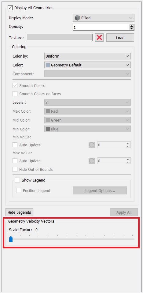
By dragging the slider to the right, the user can increase the scale factor of the vector and, consequently, their size. Dragging the slider to the left decreases the size of the vectors. Note that the widget is only enabled when at least one of the geometries has motions that are calculated through the multibody dynamics interface.
Force Averaging
To complement the motion interpolation during the EDEM simulation, forces are averaged over the number of time steps that EDEM is run for. Custom properties for the time-averaged force and torques acting on a geometry are created when the geometry is registered for control using the getGeometryID method. The average force is updated in the custom property every EDEM time step. The averaged values for the last simulation-step can be retrieved from EDEM when it is not simulating a time step. All averaged values are reset to zero at the start of the next EDEM simulation-step.
Design of Experiment Style Studies with EDEM Coupling Interface
With Version 2_1_0 and onwards of the EDEM Coupling Interface was expanded to enable geometry sections to be imported and deleted at any point in a simulation. This allows equipment designs to be evolved through co-simulation with Design-Of-Experiment (DOE) style programs or parametric CAD packages. This capability in the EDEM Coupling Interface also allows the automatic creation of many simulations for batch mode running containing variations on geometry or geometry dynamics.
Importing a Geometry
The loadGeometry method will create a new geometry section in the EDEM simulation and name it using the CAD file name which is read in. The import process will use the same default parameters as shown in the EDEM Creator Geometry import dialog, any changes to the defaults can be specified via the setGeometryImportParameters method, which should be invoked prior to calling the loadGeometry method.
Assigning a Material to a Geometry
Prior to loading a geometry, the user needs to specify the material to assign to the geometry section that's about to be loaded. The relevant ID is obtained via a call to getMaterialId.
Deleting a Geometry
Use the name of the target geometry to delete it from the simulation via a call to removeGeometry.
Assigning Kinematics to Geometry
The EDEM Coupling Interface has the ability to assign built-in kinematics to a target geometry. The kinematics are assigned using addLinearTranslationKinematic, addLinearRotationKinematic, addSinusoidalTranslationKinematic, addSinusoidalRotationKinematic, addConveyorTranslatonKinematic and addConveyorRotationKinematic.
The parameters for each of the dynamics represent the values that are available in the configuration section of ‘Add Kinematic’ GUI for the chosen kinematic type.
Compiling Coupling Interface Code to an Executable
This guide highlights how to compile a simple user written code into a stand-alone executable to work with the coupling interface. To compile the EDEM-FLUENT coupling please see the ‘Coupling EDEM with ANSYS Fluent’ E-Learning guide found on the Altair Website. To access the E-Learning Login and go to eLearning Courses > EDEM > Coupling EDEM with ANSYS Fluent.
Windows:
To create a simple executable a 3rd party compiler is required to compile C++ code. EDEM Altair does not support any specific compiler however Microsoft Visual Studio is commonly used and Visual Studio Community 2017 is shown in this example. When installing Visual Studio it is important to choose to install the C++ toolset (Universal Windows Platform development and Desktop development with c++), depending on the install these may be installed by default or additional options in the installer.
-
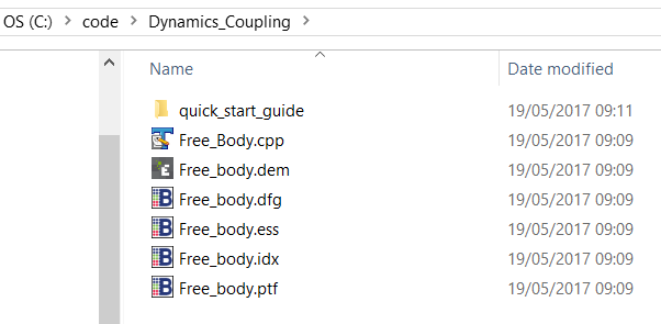
Place the .cpp files written by the user in a working directory, e.g. C:\code\Dynamics_Coupling. In this instance a Free_Body.cpp file is used which can be found on the EDEM Forum.
-
Start Visual Studio

-
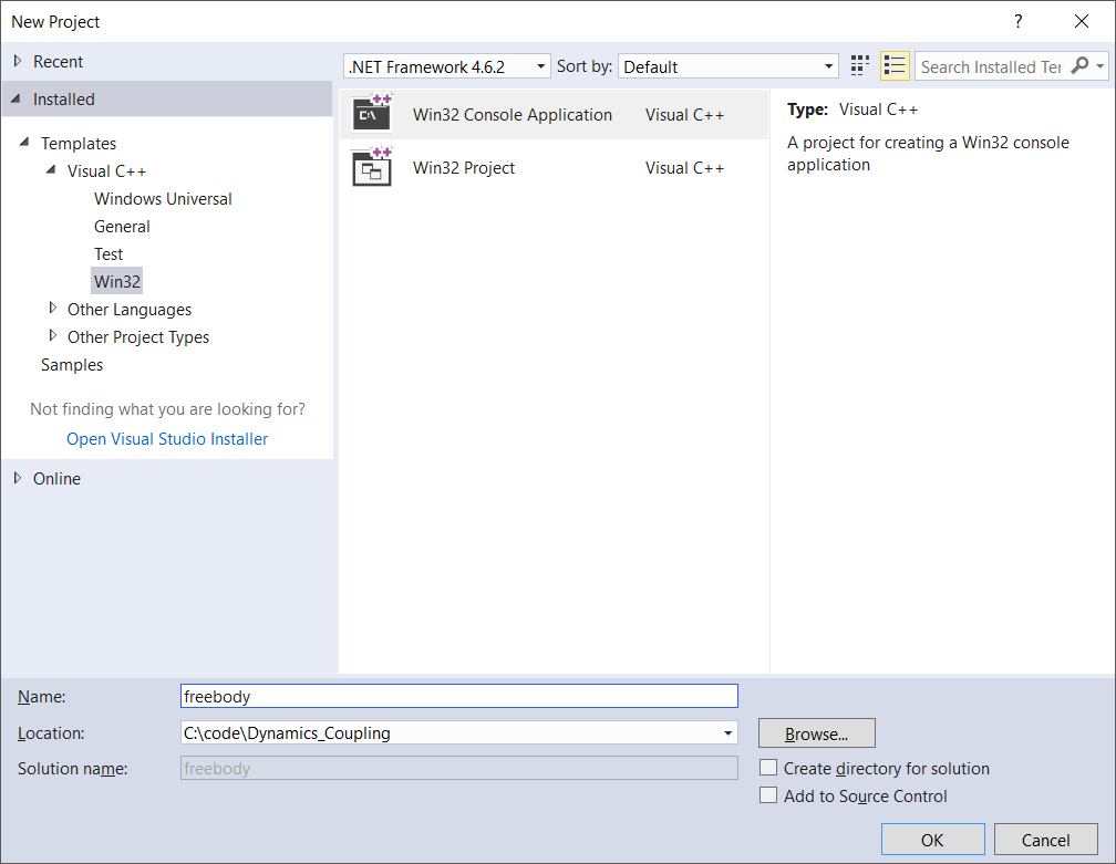
Create a New Project (Win32 Console Application Visual C++)
-
Go to File > New > Project
-
Set name: freebody
-
Set location C:\code\Dynamics Coupling
-
Choose OK
-
-
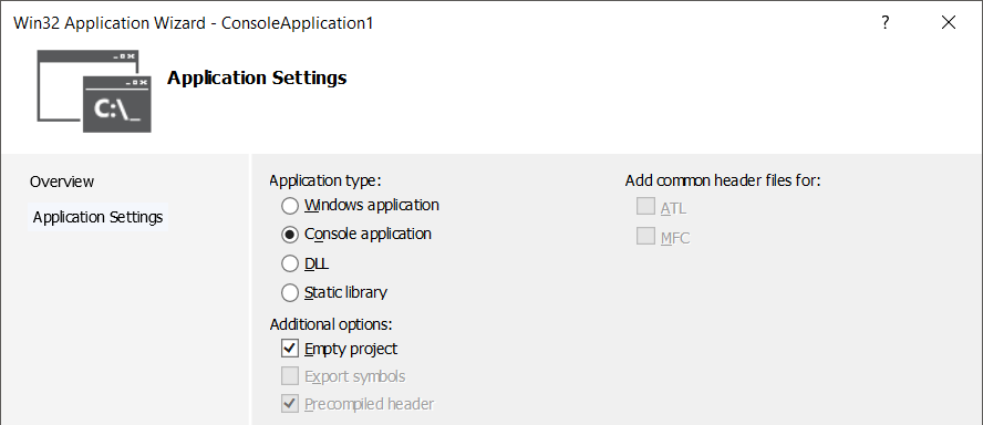
Select Application Settings
-
Choose Console Application
-
Select Empty Project
-
Click Finish
-
-
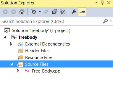
Add the file Free_Body.cpp to the project
-
Copy this file to C:\code\Dynamics_Coupling\freebody
-
Right Click on Source Files > Add > Existing Item > Free_Body.cpp > Add
-
- Go to Project > Properties and set the following:
- Configuration to All Configurations
- Platform to All Platforms
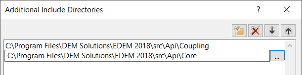
- Select Configuration Properties > C/C++ > General
- Select Additional Include Directories > <Edit…>
- Add the following paths then select OK:
C:\Program Files\Altair\2022.1\EDEM\bin\src\Api\Coupling
C:\Program Files\Altair\2022.1\EDEM\bin\src\Api\Core
-
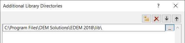
Select Configuration Properties > Linker > General > Additional Library Directories > edit
-
Include:
C:\Program Files\Altair\2022.1\EDEM\bin\lib\
-
-
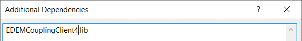
Select Configuration Properties > Linker > Input >Additional Dependencies > Edit
-
Add EDEMCouplingClient4.lib
-
OK
-
-
Go to Project > Properties > Configuration Manager and set the following:
-
Active solution configuration to Release or Debug
-
Active solution platform to x64 > close
-
Build the solution (Build > Build Solution) to create the .exe file
-
Linux:
To compile coupling interface applications for use with EDEM running on Linux, it is recommended to use the GNU Compiler Collection, more referred to as gcc.
Compiling with gcc
If you have the source code <source_code>.cpp file in your working directory, the following two commands will compile the source code:
g++ -std=c++11 -c -g -DDEMLINUX -I ~/2022.1/altair/EDEM/src/Api/Core -I ~/2022.1/altair/EDEM/src/Api/Coupling/ -MMD -MP -MF <output>.o.d -o <output>.o <source_code>.cpp
followed by:
g++ -std=c++11 -o <compiled> <output>.o -L ~/2022.1/altair/EDEM/lib -lEDEMCouplingClient4 -L ~/2022.1/altair/EDEM/bin -lQt5Core -lQt5Network
where <source_code>, <output> and <compiled> are filenames of your choosing, EDEM_XXXX is replaced with the version of EDEM you have installed, libEDEMCouplingClientXXXXX is replaced with the coupling client library version associated with it, and the libQtXXXX entries use the Qt version associated with that EDEM release. For reference, the coupling client library and Qt versions can be found below:
|
EDEM Version |
Coupling Client library version |
libQt Version |
| 2022 |
libEDEMCouplingClient4.so |
5.12 |
| 2021 | ||
|
2020 |
||
|
2019 |
5.6 | |
|
2018 |
||
|
2017.2 |
libEDEMCouplingClientV3_2_0.so |
|
|
2017.1 |
libEDEMCouplingClientV3_1_0.so |
|
|
2017.0 |
libEDEMCouplingClientV3_0_0.so |
Running an Application
When running your compiled application, you will need to ensure that the EDEM libraries can be correctly picked up, by adding the location of the EDEM libraries to the LD_LIBRARY_PATH environment variable. To do this, you will need to enter the following:
export LD_LIBRARY_PATH=$LD_LIBRARY_PATH:/opt/DEMSolutions/EDEM_XXXX/lib/
Where, again, XXXX is replaced with your EDEM version. If entering this into a console, this will only be applied in the current session. If you want to add the EDEM library path to LD_LIBRARY_PATH permanently, you will need to add this line to your .bashrc file.