FluxTubeConcept
Flux tube concept
![]()
Library
Magnetic/FluxTubes/UsersGuide
Description
Overview of the Concept of Magnetic Flux Tubes
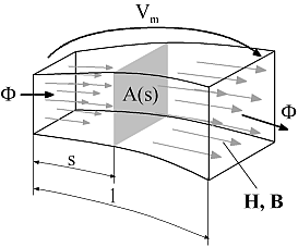
Following below, the concept of magnetic flux tubes is outlined in short. For a detailed description of flux tube elements, please have a look at the listed literature. Magnetic flux tubes enable for modeling of magnetic fields with lumped networks. The figure below and the following equations illustrate the transition from the original magnetic field quantities described by Maxwell's equations to network elements with a flow variable and an across variable:

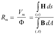
For a region with an approximately homogeneous distribution of the magnetic field strength H and the magnetic flux density B through cross sectional area A at each length coordinate s (A perpendicular to the direction of the magnetic field lines), a magnetic reluctance Rm can be defined:

With the definition of the magnetic potential difference Vm as an across variable and the magnetic flux Φ as flow variable, a reluctance element Rm can be defined similar to resistive network elements in other physical domains. Using Maxwell's constitutive equation

the general formula for the calculation of a magnetic reluctance Rm from its geometric and material properties is:

For a prismatic or cylindrical volume of length l and cross sectional area A with the magnetic flux entering and leaving the region through its end planes, the above equation simplifies to:

Similar equations can be derived for other geometries. In cases where a direct integration is not possible, the reluctance can be calculated on base of average length, average cross sectional area and volume V respectively:

Network elements for sources of a magnetic potential difference or magnetomotive force, i.e., coils or permanent magnets can be formulated as well. The resulting magnetic network models of actuators reflect the main dimensions of these devices as well as the normally nonlinear characteristics of their magnetically active materials.