Category: Toolbox > eDrives and Systems > eDrives > Inverters
Inputs:
•Vdc: DC bus voltage (V).
•EN[l,2,3]: Enable pins for three phases.
•Duty[1,2,3](0..1): Duty cycles for three phases.
•Iout[1,2,3]: The output (load) current (A) fed back into the three-phase inverter bridge model.
Outputs:
•Vout[1,2,3]: Three-phase line-to-neutral output voltage (V).
•Vout[12,23,31]: Three-phase line-to-line output voltage (V).
•lin: The DC input current (A) of the model.
•v_lsense[1,2,3]: Three-phase output of the voltages (V) dropped across the internal current sense resistors.
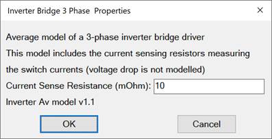
Description: The Inverter Bridge-3 Phase block is an average model of a three-phase inverter bridge. This block includes the current sensing resistors measuring the switch currents. The voltage drop is not modeled.

Current Sense Resistance (mOhm): Specifies the resistance value of the three-phase current sensing resistors. The output at v_Isense will then be Iout*Rsense for each of the three phases.