EDEM Analyst
You can play back the simulation, graph results, save a still image, and create a video or export data.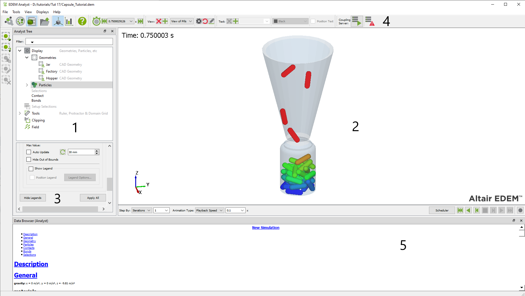
- Analyst Tree
- Viewer
- Section Details
- Toolbar and Menu Bar
- Data Browser
Analyst Tree
The Analyst Tree is displayed on the left side of the EDEM window and comprises five sections - Display, Setup Selections, Tools, Clipping, and Field.
Right-clicking on any section of the Analyst Tree allows you to expand/collapse all the corresponding subsections.
Viewer
The Viewer displays 3D representations of your particles, geometry, and fields (if applicable). The rotation, position, and zoom factor of the Viewer are controlled using the mouse.
A number of animation controls appear below the Viewer.
Section Details
The Section Details space contains all the information and configuration options for each of the sections of the Analyst Tree. The options displayed within the Section Details depend on the section or subsection being highlighted in the Analyst Tree.
Analyst Toolbar
| Icon | Name | Description |
|
|
Creator | Click to switch to the Creator. |
|
|
Simulator | Click to switch to the Simulator. |
|
|
Analyst | Click to switch to the Analyst. |
|
|
Open | Click to open an existing model. |
|
|
3D Viewer | Click to switch to the 3D Viewer. |
|
|
Create Graph | Click to switch to the Graph Creator. |
|
|
Help | Click to view the online help. |
|
|
Jump to Start | Move to the first Time Step in the simulation. |
|
|
Animate Backwards | Click to continually change Time Steps backwards. |
|
|
Step Backwards | Click to step backwards. |
|
|
Stop Animation | Click to stop animation. |
|
|
Step Forwards | Click to step forwards. |
|
|
Animate Forwards | Click to continually change Time Steps forwards. |
|
|
Jump to End | Moves to the last Time Step in the simulation. |
|
|
Record Animation | Click to open the Animation dialog box. |
|
View: |
Save View | Save the current View settings. |
|
View: |
Delete View | Delete the selected View settings. |
|
|
Start Coupling Server | Click to start the Coupling Server. |
|
|
Server Awaiting Connection | Shows the Server is started but not connected. |
|
|
Server Connected | Shows the Server is connected. |
|
|
Coupling Server Disabled | Shows the Server is not running. |
|
|
Stop Server | Click to stop the Coupling Server. |
|
Text: |
Add Text | Click to add text to Viewer. |
|
Text: |
Delete Text | Click to delete text from the Viewer. |
|
|
Add Selection | Adds a Selection to the analysis. |
|
|
Manual Selection | Adds a Manual Selection. |
|
|
Grid Bin Group | Adds a Grid Bin. |
|
|
Geometry Bin | Adds a Geometry Bin. |
|
|
Mass Flow Sensor | Adds a Mass Flow Sensor. |
|
|
Total Mass Sensor | Adds a Total Mass Sensor. |
|
|
Velocity Profile Sensor | Adds a Velocity Profile Sensor. |
|
|
Segregation Sensor | Adds a Segregation Sensor. |
|
|
Density Sensor | Adds a Density Sensor. |
|
|
Imported Geometry Bin | Adds an Imported Geometry Bin. |
|
|
Copy Selection Group | CopiesSelection Group. |
|
|
Rename Selection Group | Renames Selection Group. |
|
|
Deletes Selection Group | Deletes Selection Group. |


Analyst Menu Bar
File Menu
-
Open opens an existing model.
-
Truncate File removes sections of data from your model.
-
Export opens a submenu with the following options:
-
Simulation Deck allows you to export a single, full-Time Step from your simulation to create a copy as a new EDEM simulation deck (you cannot export from partial save Time Steps). Exporting a deck allows it to be transferred to another location and run using identical simulation parameters. To export a simulation deck:
-
Use the Animate Forwards or Animate Backwards tool to change the simulation Time Step to the value that you want to export. EDEM will save this as a new simulation.
-
Navigate to File > Export > Simulation Deck.
-
Specify a name for the deck and then click Save.
-
In the Export Options dialog box, select the content options:
-
Unselecting the Export Custom Properties allows you to exclude any custom property data from the deck.
-
Nullify Stored Factory Activities allows you to remove the factory history from the exported simulation file. For example, if a dynamic factory is set to create X kg of a material starting at 1s, and the factory has run so that this mass of material has been created, EDEM sets the factory as completed. If you export with the Nullify checkbox selected, then the factory will no longer be set as completed. If the Start Time is set prior to the factory start time, this factory will restart in the new Simulation Deck.
-
Set Simulation Time allows you to change the displayed simulation time of the exported input deck. This does not change simulation results. This is designed to help when coupling to other CAE tools with different simulation time. Enter a starting time in seconds.
-
-
Click OK to save the simulation deck.
-
-
Breakage Analysis
-
Results Data allows you to export specified data for analysis.
-
SimSolid Data allows you to export force data on a specific geometry in a text format suitable for SimSolid import.
-
Timestep Selection allows you to select the Start Time Step and End Time Step. Data can be exported for a single Time Step (where Start and End Time Steps are equal or Timestep per file is selected) or as time-averaged values (where the Start and the End Time Steps differ and Average to file is selected) to minimize the effects of spiking.
-
Force Export
-
Orient and transpose to initial CAD position maps the force data to the initial CAD position for each Time Step. This setting allows structural analysis to be carried out in SimSolid even if the geometry has moved position in EDEM.
-
Contact Force allows you to export force data per particle-geometry contact point.
-
Element Force allows you to export force data per geometry mesh element.
-
Geometry allows you to select the geometry part for which data is to be exported.
-
-
Material Center of Mass Export allows you to select a pre-defined particle (manual selection) in order to export the X, Y, and Z co-ordinates of the center of mass and the total mass for the selection.
-
Export writes the .csv file containing the load data for importing into SimSolid and the file containing the information on the particle manual selection.
-
-
HyperMesh Workbench Data exports pressure and force data on a specific Geometry in a text format suitable for HyperMesh import.
-
Timestep Selection allows you to select Start Timestep and End Timestep. Data can be exported for a single Time Step (where Start and End timesteps are equal or ‘Timestep per file’ is selected) or as time-averaged values (where the Start and the End Time Steps differ and ‘Average to file’ is selected) to minimize the effects of spiking.
-
Force and Pressure Export
-
Geometry allows you to select the Geometry part for which data is to be exported.
-
Element Pressure allows you to export pressure data per Geometry mesh element.
-
Element Force allows you to export force data per Geometry mesh element.
-
Contact Force allows you to export force data per particle-Geometry contact point.
-
Orient and transpose to initial CAD position allows a transient analysis to be performed in HyperMesh without the Geometry moving from its initial position. For each Time Step the force and pressure data is mapped to the initial position.
-
-
Material Center of Mass Export allows you to select a pre-defined particle (manual selection) in order to export the X, Y, and Z co-ordinates of the center of mass and the total mass for the selection.
-
Export allows you to write the .csv file containing the load data for importing into HyperMesh and the file containing the information on the particle manual selection.
-
-
ANSYS Workbench Data allows you to export pressure and force data on a specific Geometry in a text format suitable for ANSYS import.
-
Timestep Selection allows you to select Start Timestep and End Timestep. Data can be exported for a single Time Step (where Start and End timesteps are equal or ‘Timestep per file’ is selected) or as time-averaged values (where the Start and the End Time Steps differ and ‘Average to file’ is selected) to minimize the effects of spiking.
-
Force and Pressure Export
-
Geometry allows you to select the Geometry part for which data is to be exported.
-
Pressure allows you to export pressure data.
-
Force allows you to export force data.
-
Orient and transpose to initial CAD position allows a transient analysis to be performed in ANSYS without the Geometry moving from its initial position. For each Time Step the force and pressure data is mapped to the initial position.
-
-
Material Center of Mass Export allows you to select a pre-defined particle manual selection in order to export the X, Y and Z co-ordinates of the center of mass and the total mass for the selection.
-
Export allows you to write the .axdt file containing the load data for importing into ANSYS and the file containing the information on the particle manual selection.
-
-
Image allows you to save a copy of the image currently displayed in the Viewer.
-
Breakage Particle Size Distribution
-
Timestep defines the Time Step at which breakage should be analyzed.
-
Breakage Particle defines particles which break.
-
Postpro Particle defines dummy particles.
-
Lambda defines a material parameter involved in the distribution of fines. EDEM provides an automatic estimate based on other material parameters (see Tavares and Changas 2020).
-
Output file (.csv) allows you to select the location to which the csv file should be saved.
-
Display Graph of Results plots a graph of the Particle Size Distribution.
-
Save Graph of Results allows you to select a location where you want to save the graph of the particle size distribution.
-
Select Geometry Bin allows you to select geometry bins without rotation. Geometry bins with rotation are not supported.
-
-
Data to Stl. Export geometries and particles to a CAD file
-
Particles
-
Export either spheres or templates exports Multi-Sphere shapes. An input template CAD will apply a template to the particle.
-
Particle Output file generates a name for the exported .stl.
-
Global Particle Scale applies a single value scale to the spheres/templates. This will use the correct particle position but adjust the size of the particles based on the input scale.
-
Time Step Selection allows you to select the appropriate Time Step for the particle export.
-
-
Geometries
-
Geometry Output file generates a name for the exported .stl.
-
Merge Output Files combines all exported geometries into a single file. If not selected, each geometry will be exported as an individual file.
-
Geometry Time Step allows you to select the appropriate Time Step for the geometry export. Deformed geometries are not exported.
-
-
-
-
Print Image prints a copy of the image currently displayed in the Viewer.
-
Running an EDEMpy Script runs an EDEMpy Analyst by navigating to File > Run EDEMpy script. From this interface, a previously generated EDEMpy script can be selected. Additional arguments used in the script can be passed to python in the Arguments section.
-
Import Config imports a config (*.dfg) file.
-
Export Config exports3 a config (*.dfg) file.
-
Creator allows you to switch to the Creator.
-
Simulator allows you to switch to the Simulator.
-
Analyst allows you to switch to the Analyst.
-
Recent Files displays a list of recently opened files. Select a file to open it.
-
Quit quits EDEM.
Tools Menu
The EDEM Analyst menu is similar to the Simulator's Tools menu.
- Abaqus Co-Simulation
Is displayed when you select Abaqus Coupling in Tools > Options > Coupling Options. The Abaqus Co-Simulation dialog box is used for running Abaqus FEA simulation decks using EDEM contact data as an input. Abaqus Co-Simulation is supported for Abaqus 6.16 and newer.
-
Units
You can use EDEM specified units or SI units. -
Timestep Selection
Select Start and End Time Steps for analysis. For Static Mode cases, the Start Time Step defines the time that contact data in EDEM is used for input in the Abaqus FEA analysis. Start and End Time Steps define the start and end times for Averaged Mode (loads averaged over time) and Dynamic Mode (dynamic loads over time). Step Factor defines the sampling frequency to use for averaged and dynamic cases. -
Geometries to Include
Select the geometries in EDEM to include in the analysis. Only contacts on selected geometries are transferred to Abaqus. -
Abaqus Solver
Define the path to Abaqus launcher and if Abaqus is to be solved remotely define the Host and Port for this connection. Select Auto-Invoke Local Abaqus Solver for cases solved on the local machine – Abaqus solvers must be manually invoked if they are run remotely. -
Abaqus Files
Define the Abaqus input (.inp) and output (.odb) files.
-
View Menu
-
Show Particles
Turns the particle display in the Creator on or off. -
Themes
Displays the EDEM interface with the Legacy (default) or Dark Theme.
Displays Menu
Splits the EDEM view window into multiple displays, allowing multiple viewer windows to review different view-points of the model within each window.
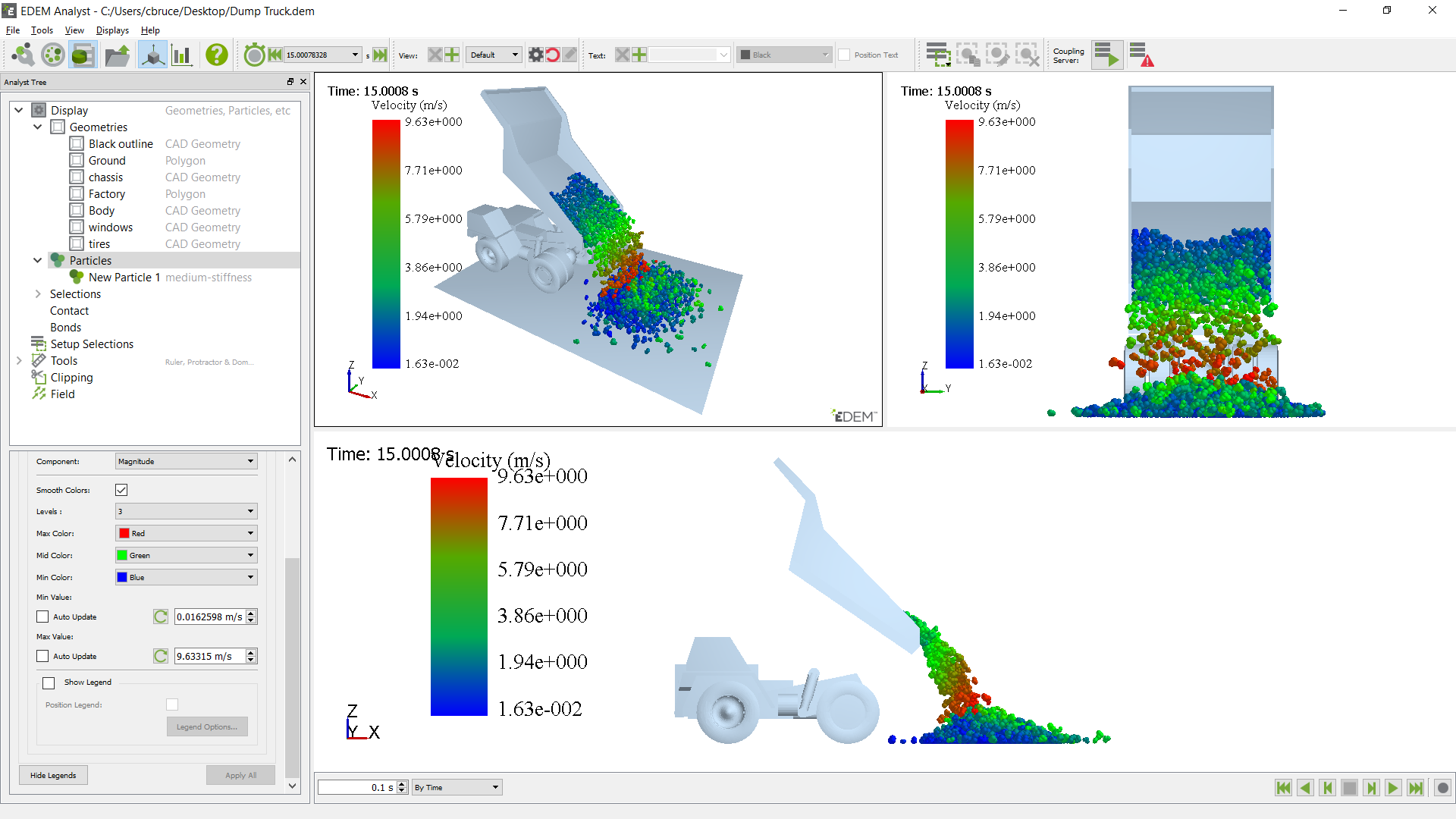
Views and graphs can also be displayed side by side using split displays so that simulations may be simultaneously reviewed qualitatively and quantitatively on the same display.
The following example shows particles visualized by mass from two view points and a line graph of total compressive force acting on the body of the Dump Truck.
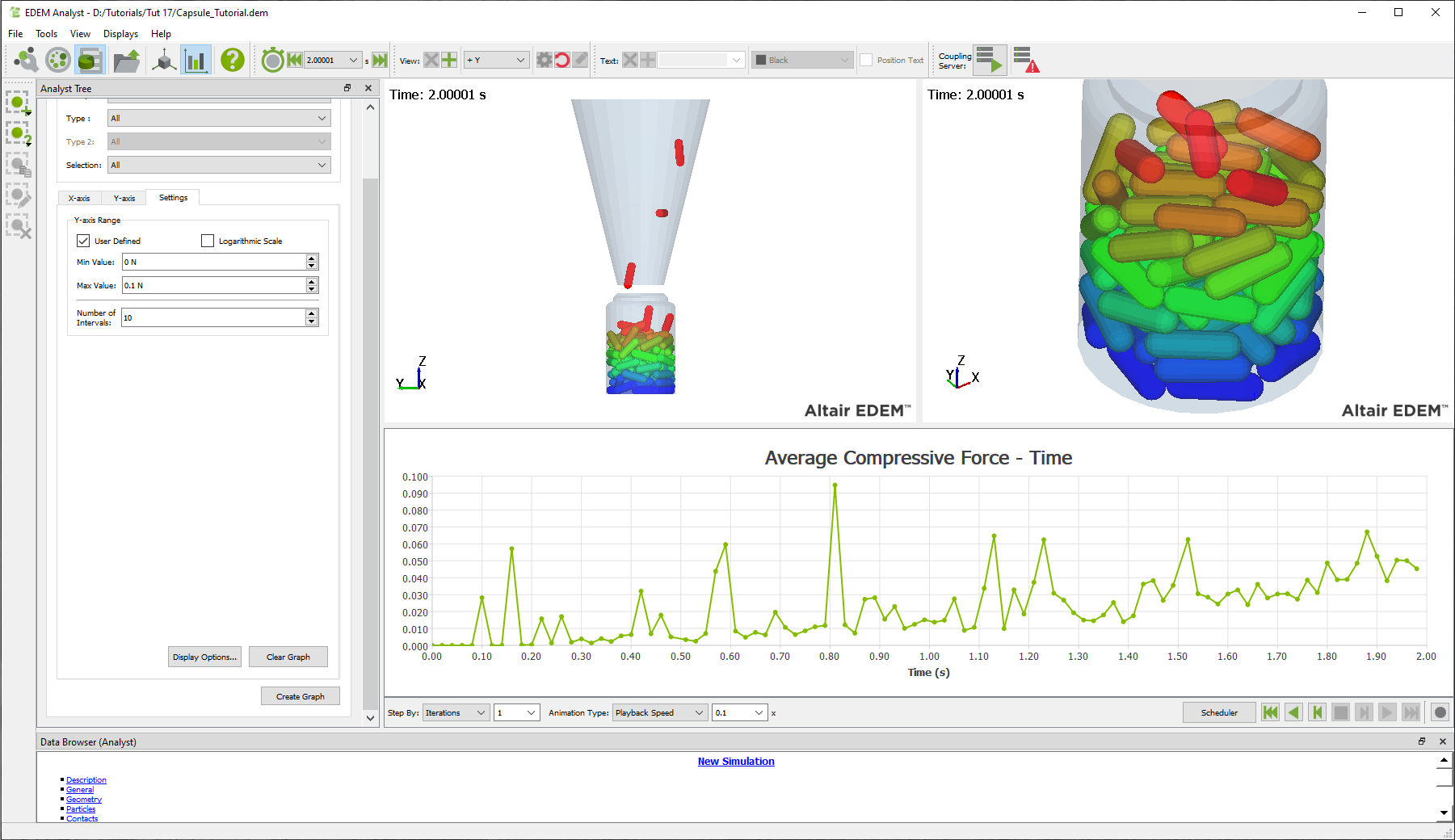
Image and video exports maintain the same display layout so that exported images and videos combine views and graphs.
Selecting a display setting option overwrites the previous display settings.
Help Menu
- Help
Provides relevant information regarding the EDEM interface. - About EDEM
Provides information about the current version of EDEM. The EDEM Version and Revision number are useful for EDEM technical support when discussing support cases. - About Altair Simulations Products
Provides access to the Copyright notices, Altair website, License Agreements, and Customer Support.
Data Browser (Analyst)
The Data Browser is a .html page that displays detailed information about your model. The information displayed differs between the Creator, Simulator, and Analyst. Right-click in the Data Browser and select Save to save the information in an .html file.
The Data Browser (Analyst) comprises the following sections:
Description
The description is provided in the Project section of the Analyst Tree.
General
-
Gravity
Displays details of the gravity acting in your model as specified in the Globals pane. -
Materials
Lists all materials used in the model and their properties, as specified in the Materials Editor. -
Energy
Displays the total energy in the model at the current time, which is the sum total of the kinetic energy, potential energy, and the energy in any contacts taking place.
-
Dimensions
Displays the number of dimensions in your domain.
Geometry
-
Domain
Lists the dimensions of the domain as specified in the Geometry pane. -
Geometry Totals
Totals the details of the number of elements that make up each section of the geometry. -
Sections
Lists each section(model) and its properties.
Particles
-
Particles
Lists each particle type used in the model and their properties. Details of each surface within the particle are also listed. Properties are as specified in the Particles pane. -
Factories
Lists the details of each factory used in the model and their properties. Properties are as specified in the Factory pane. The total number of particles created by each factory is also listed. -
Particle totals
Lists the total number of particles in the model at the current time. Totals for each particle type are also listed.
Contacts
-
Interactions
Lists the interaction types taking place in the model as specified in the Materials Editor. -
Contacts
Lists the total number of contacts in progress at the current time. The contacts are broken down into contact types: for example, the number of particle A - particle B contacts or particle B - surface A contacts. The total number of collisions that have taken place during the Time Step are also listed.
Bonds
-
Lists the bond totals, indicating the total number of bonds, total number of intact bonds, total number of broken bonds, and total intact and broken bonds for each particle type.
Selections
-
Lists all selections
Links to pages with information on the selection and its associated queries, list of particles, and geometry elements (if applicable).
(c) 2023 Altair Engineering Inc. All Rights Reserved.