The Multi Body Dynamics Coupling Interface
Its primary function is to allow users to perform simulations with programmatic control of geometry motion and physics, allowing implementation of complex motions, rigid body physics or coupling with advanced Multibody dynamics codes.
The following diagram represents the Multibody Dynamics Coupling Interface data interaction with EDEM.

The Multibody Dynamics Coupling Interface allows the exchange of contact forces and equipment motion between EDEM and a coupled code. The coupled code can retrieve bulk material forces resulting from contact with the equipment surfaces calculated in EDEM and return equipment kinematics.
The simplicity of the data exchange method between EDEM and coupled Multibody dynamics code allows for the rapid development of rigid body dynamics for inclusion in DEM simulations. The control over EDEM simulations offered by the interface is also suitable to allow coupling and co-simulation with 3rd party Multibody dynamics software such as LMS Virtual Lab Motion, Matlab Simulink, and MSC Adams. Through coupling with MBD software, modeling can be extended to contain a wide range of components including hydraulic control systems, motors and interconnected equipment geometries.
Initiating the Coupling Interface sections
The Coupling Interface has a series of initiation flags. These flags allow you to predefine what functionality the coupling script will use. The current list of flags can be found in the CCouplingFeatureFlags class in ApiTypes.h. Older coupling codes written prior to this functionality will run without the flags being defined. However, they will not benefit from the performance improvement.
Registering Geometries for Motion
Geometries in EDEM are easily identifiable by their readable names. However, to maintain computational performance during simulation using the Multibody Dynamics Coupling Interface, geometries are identified by an unique integer ID. The method also registers the coupling for control using the Coupling Interface.
Use the getGeometryID method to retrieve the unique integer ID of geometries that are controlled by the Multibody Dynamics Coupling Interface at the start of every simulation. This method not only returns the unique ID, it also registers the geometry for control using the a number of geometry custom properties. These properties are required to implement the functionality of coupled equipment dynamics.
Geometries that are not registered for control using this method will not return forces or accept motions set using the Multibody Dynamics Coupling Interface during simulation.
Retrieving the Position of a Geometry
The position of a geometry can be requested from EDEM at any point in a coupled code when EDEM is not executing simulate using the getGeometryPosition method . The data returned from the method is the position of the center of mass of the geometry (defined before simulation via the EDEM Geometry tab in the GUI) and the orientation of the geometry on the current EDEM Time Step.
To establish how far a geometry section has moved since the start of the simulation use the getGeometryTranslation method.
Setting Geometry Motion
There are three groups of parameters related to setting a geometry motion using the setGeometryMotion method:
- Total translation & Orientation - A geometry controlled using the Multibody Dynamics Coupling Interface can have two components of motion, a linear displacement and a rotational displacement about a point of action. The linear displacement is set as the total translated distance the geometry has undergone from its starting position in EDEM. motion/position of a geometry is set using a total translation value from the starting position to avoid the accumulation of a positional error between EDEM and the Dynamics Code.
Rotational displacement is expressed as an orientation using a 3x3 rotational matrix, acting about a point of action, defined for the geometry. By default, a geometry’s point of action is set the same as its center of mass. This can be changed using the setGeometryPointOfAction method. - Velocity & Angular Velocity - The geometry’s linear and angular velocity are not used to determine the position of the geometry in the EDEM simulation. They are used in the resolution of particle to geometry contacts in the contact model and therefore have an outcome on the collision force resolution and overall behavior of the EDEM physics. User-defined velocity and angular velocity are stored in custom properties that are created when a geometry is registered for control by the dynamics coupling using the getGeometryID method.
- Time & Motion of Point of Action - The third group of parameters determine the final options that are required for implementing the geometry motion. These are the time over which the action should be and a variable telling EDEM whether the point of action of rotation is moved with any translation applied to the geometry, or not.
Motions can be set to act over multiple EDEM time steps to reduce the communication overhead on the coupling. For details on how this is achieved, see the following section on Geometry Motion Interpolation.
An optional parameter allows you to determine whether the point of action of their geometry will move with the translation of the geometry, or not. In the vast majority of simulations this will be the case, and, as such, the option is selected by default. However, should you wish to control the point of action, independently of motion, the option can be set to false.
Deformable Geometries with the Multibody Dynamics Coupling Interface
The EDEM Coupling Interface can deform a geometry by setting or offsetting the geometry nodes local or global positions using one of the following methods:
setLocalNodePositions
setGlobalNodePositions
setAllLocalNodePositions
setAllGlobalNodePositions
offsetLocalNodePositions
offsetGlobalNodePositions
offsetAllLocalNodePositions
offsetAllGlobalNodePositions
The “set” methods directly sets the node position to the point fed in the Method. The “offset” methods moves the nodes a set distance from their current position.
Associated to those functions, methods to get the forces on the triangles, nodes as well as methods to get the triangles and nodes ID are available.
Retrieving Material Forces Acting on Geometries
Using getGeometryForces, it is possible to retrieve the summed material force and torque acting on the specified geometry. The torque is calculated about the specified point of action for the geometry. With these data it should be possible to calculate the dynamic response of the equipment represented by the geometry.
Setting Point of Action on a Geometry
The point of action of a geometry is set to the same value as its center of mass, by default. If rotations of a geometry occur from a point other than the center of mass, it is possible to change this value using the setGeometryPointOfAction method. This operation should be performed at the beginning of a simulation in the majority of cases.
The point of action of a geometry is relevant to two of the methods provided by the Multibody Dynamics Coupling Interface. It determines the position of the center of rotation for a change in a geometry’s orientation when setting motion and the point about which torque acting on the geometry is calculated.
Multi-Step Simulation with the Multibody Dynamics Coupling Interface
The EDEM Coupling Interface supports multiple time steps. Since the introduction of EDEM v2.0.0 and the introduction of the Multibody Dynamics Coupling Interface, changes have been made to improve the performance of coupled simulations.
The most significant change is the ability to pause EDEM simulations between simulation-steps, where previously the EDEM simulation was effectively stopped while the coupled application performed its simulation-step. By specifying the total Simulation Time alongside the simulation-step time using the simulate method, EDEM can determine whether the simulation has completed or not, and pause or stop, as appropriate.
Multiple time steps can be simulated in EDEM, between data exchanges, when using the Multibody Dynamics Coupling Interface. In the appropriate situation, this significantly reduces the computational overhead of the messaging exchange. To provide this functionality, the Multibody Dynamics Coupling Interface includes automated motion interpolation and force averaging for multiple-step simulate commands.
Geometry Motion Interpolation
Geometry motion can be implemented over multiple time steps using the setGeometryMotion command. By specifying an ‘action time’ that is greater than the Time Step that EDEM is set to use, the motion of a geometry is automatically interpolated over the specified number of time steps.
Geometry motion is linearly interpolated in both linear (translation) and spherical (orientation) components of motion. The linear interpolation is performed using the LERP algorithm and spherically using the SLERP algorithm.
There are some best practices to ensure that the desired results are achieved:
- When setting an action time on a geometry, it should be set for a multiple of an EDEM Time Step. Motions are guaranteed to be completed for the last Time Step, therefore the result of setting a fractional action time is that the motion will be completed up to one Time Step before EDEM completes its simulation step.
- Linear interpolation always acts in a straight line between two points. Therefore non-linear motions will have a degree of positional error associated with them. This should be considered when selecting an appropriate data exchange interval.
- Spherical linear interpolation always acts on the minimal path. Therefore a motion with an orientation change of over 180 will result in rotation in the opposite direction (this is the minimal path).
- Spherical linear interpolation with an orientation change of exactly 180 is undefined. There are an infinite number of paths to achieve this. Therefore setting a motion with an orientation change of 180 can result in undefined behavior.
- The geometry velocities input using setGeometryMotion is maintained for the duration of the movement and therefore there is an effect on the particle-equipment contact results. For the vast majority of DEM simulations, equipment accelerations are significantly lower than those of the material interacting with them and changes in geometry velocity should not be extreme. Time step ratios of the order of 10 should not have an appreciable effect on the results of a simulation.
The precise sensitivity of the time step ratio is simulation-dependant. It is important that users determine their own acceptable ratio through appropriate numerical experiment. - Geometry Velocity Vectors: Geometries that have an associated velocity vector will be rendered in the Analyst with an arrow to indicate the direction of motion of the geometry. The arrow is drawn using the velocity field of the target geometry. To ensure that the velocity vector is displayed correctly, care should be taken when calculating the geometry velocity so that each of the velocity vector's components [x, y &z] are catered for e.g. if the geometry's motion is along the y-axis only, then the x and z components of the velocity vector should be explicitly set to zero. Failure to implement this functionality could result in the geometry velocity vector not being displayed as intended /expected.
Geometry Velocity Vectors
A geometry velocity vectors widget has been added to the Analyst's Model tab to enable you to increase or decrease the size of the vectors.
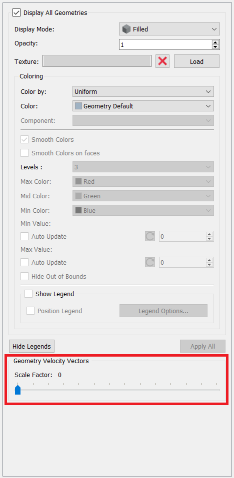
By dragging the slider to the right, you can increase the scale factor of the vector and, consequently, their size. Dragging the slider to the left decreases the size of the vectors.
Force Averaging
To complement the motion interpolation during the EDEM simulation, forces are averaged over the number of time steps that EDEM is run for. Custom properties for the time-averaged force and torques acting on a geometry are created when the geometry is registered for control using the getGeometryID method. The average force is updated in the custom property every EDEM Time Step. The averaged values for the last simulation-step can be retrieved from EDEM when it is not simulating a Time Step. All averaged values are reset to zero at the start of the next EDEM simulation step.
(c) 2023 Altair Engineering Inc. All Rights Reserved.