Creator Tree-Geometries
The Creator Tree-Geometries allows you to use geometry sections, such as pipes or mixing drums, to construct the environment in which your bulk material interacts. You can make section definitions in EDEM or import them from a CAD (or comparable) program. They can be used to create particle factories.
You can use any number of sections in a model to build complex machinery. You can use an n-sided polygon, box, or cylinder to define sections. Each section contains several triangular components. For example, a ten-sided polygon has ten elements and a square surface has two elements.
Creating a new section
-
Right-click Geometries in the Creator Tree.
-
Right-click > Add Geometry and select Box, Cylinder, or Polygon. You can also use the Icon System.
-
Right-click the selected Geometryand rename as appropriate.
-
Select Geometry to view the General Properties.
| Properties | Description |
|
Volume |
A section is described as a volume or a surface. Completely closed boxes and cylinders are volumes; polygons and open boxes or cylinders are surfaces. This field is completed automatically. Volumes or virtual surfaces can later be turned into particle factories. |
|
Material |
Select a Geometry material from the drop-down list. |
|
Type |
A section is either Virtual, Physical or Dynamic Domain. A physical section is an actual surface or volume that particles can interact with. A virtual section (used to create particle factories) is a surface or volume of interest that does not actually exist and does not interact with anything in a simulation. A Dynamic Domain can only be applied to an EDEM Box geometry (volume). If the Simulator Dynamic Domain option is checked then any particles inside the Dynamic Domain will be active and particle contacts and forces are calculated as usual. Any particles outside the dynamic domain will be assessed to determine if they are stationary. Any stationary particles will be frozen and removed from the contact detection calculations, allowing the simulation to be resolved faster. |
|
Parent |
Allows users to define a Geometry object to be a parent if using the parent child functionality. |
Expand the section in the Creator Tree to view the Mass, Electrostatics (if appropriate), Transform, and Section Properties.
| Property | Description |
|
Mass |
|
|
Electrostatics |
|
|
Box |
|
|
Cylinder |
|
|
Polygon |
All polygons, except a four-sided polygon are defined as follows:
A four-sided polygon is specified as follows:
|
|
Transform |
See Section on Transform below |
Geometry sections outside of or directly coincident with the domain boundary do not partake in the simulation, and will be 'invisible' to particles.
The Transform Menu
The Transform menu allows you to define the position and orientation of your Geometry. The menu is the same for imported CAD parts, boxes, cylinders and polygons. Transforms can be applied globally or locally.
| Position |
|
| Rotation |
|
| Local Axis Rotation |
|
| Local Origin Offset |
|
Alternative Rotation Options
Use the secondary rotation option to rotate an object about a Vector.
| Start Point |
|
| End point. |
|
| Angle |
|
| Apply |
|
The axis key for the transform can be turned On or Off by navigating to View > Geometry Origin Axes and then selecting/unselecting the option.
Examples of Geometry Sections Parts
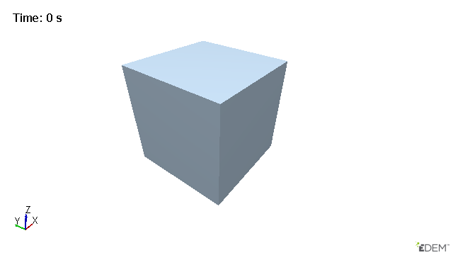
Closed Box
|
|
|||
|
|
Length (m) |
Position (m) |
Rotation (rad) |
|
X |
0.5 |
0.5 |
0 |
|
Y |
0.5 |
0.5 |
0 |
|
Z |
0.5 |
0.5 |
0 |
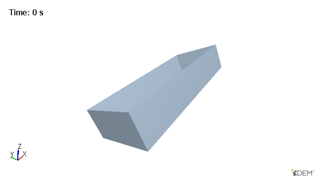
Open Tilted Cuboid
|
|
|||
|
|
Length (m) |
Position (m) |
Rotation (rad) |
|
X |
0.5 |
0.5 |
-0.5 |
|
Y |
0.2 |
0.5 |
0 |
|
Z |
0.1 |
0.5 |
0 |
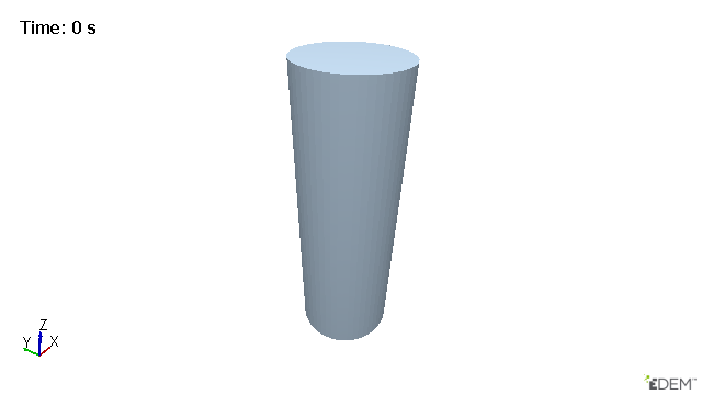
Vertical Cylinder
|
|
||||
|
|
|
Position (m) |
Rotation (rad) |
|
|
Radius Start (m) |
0.1 |
X |
0.5 |
-0.5 |
|
Radius End (m) |
0.1 |
Y |
0.5 |
0 |
|
Length (m) |
0.6 |
Z |
0.5 |
0 |
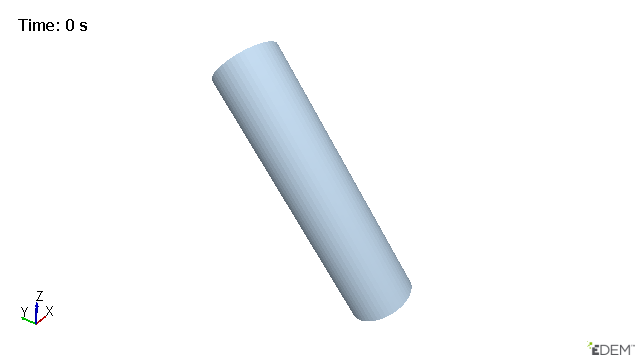
Cylinder Tilted in the y Direction
|
|
||||
|
Position (m) |
Rotation (rad) |
|||
| Radius Start (m) |
0.1 |
X |
0.5 |
-0.7 |
| Radius End (m) |
0.1 |
Y |
0.75 |
0 |
|
Length (m) |
0.78 |
Z |
0.5 |
0 |
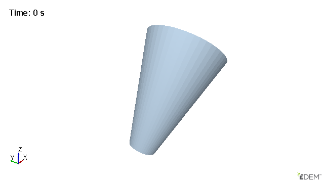
Funnel Tilted in the x Direction
|
|
||||
|
|
|
|
Position (m) |
Rotation (rad) |
|
Radius Start (m) |
0.1 |
X |
0.7 |
0 |
|
Radius End (m) |
0.3 |
Y |
0.5 |
0.7 |
|
Length (m) |
0.78 |
Z |
0.5 |
0 |
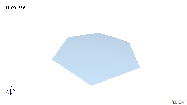
6-sided Polygon
|
|
|||
|
|
Position (m) |
Rotation (rad) |
|
|
Radius |
X |
0.7 |
0 |
|
0.5 |
Y |
0.5 |
0 |
|
|
Z |
0.5 |
0 |
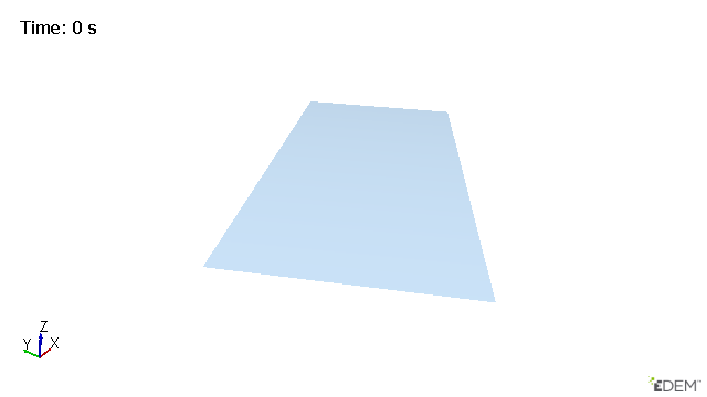
4-sided Tilted Polygon
|
|
|||
|
Length A |
|
Position (m) |
Rotation (rad) |
|
1 |
X |
0.5 |
0 |
|
Length B |
Y |
0.5 |
0 |
|
1 |
Z |
0.2 |
0.5 |
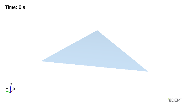
3-sided Polygon
|
|
||||
|
Position (m) |
Rotation (rad) |
|||
|
Radius |
X |
0.5 |
0 |
|
|
0.5 |
Y |
0.5 |
0 |
|
|
Z |
0.3 |
0 |
||
Parent Child Functionality
Geometry handling in EDEMenables Geometry sections to be defined as ‘children’ of another geometry section. This allows the ‘child’ geometry to inherit kinematics from the ‘parent’ geometry which greatly reduces the number of kinematics which need to be created in complex systems. At this point, the primary benefit of this change is the ability for the Dynamic Domain to be defined as a child of another geometry section without the need for movement to be controlled by an external 3rd party, such as MBD software.
Once you have defined the hierarchy in the tree, it can be identified by the indent relative to the parent Geometry as follows:
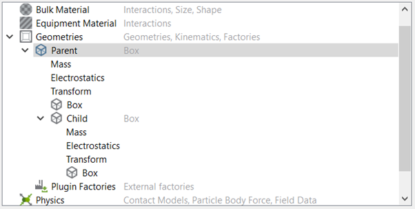
The child will now move with the parent if the parent is assigned a motion or is moved within global space (rotated or translated).
Before setting the initial position of the parent geometry, you must assign the child and select or deselect the Include Rotation From Parent Transform checkbox (located within the child's Transform). This will mitigate any unwanted movements when selecting or deselecting this option.
Partial Parent Transform
To include only a partial parent transform, there is an option within the Child’s Transform to not include the rotational aspect of the parent’s motion. Navigate to Geometry > Parent Geometry > Child Geometry > Transform > Partial Parent Transform. Deselect this option to only retain the parent translational motions.
Specifying Geometry Motions
Sections of geometry can be static or dynamic. Static sections remain in a fixed position during the course of a simulation whereas dynamic sections move. Sections can move under fixed translation, rotation, conveyor motion, or sinusoidal motion.
Specifying a Kinematic
When you use kinematics to define the equipment, they will not move when a force provided by another element is applied. For example, a section will not move when another section comes into contact with it or when a particle bounces off it. Sections pass through each other when they come into contact.
Specifying a Translation
-
Select the required Geometry in the Creator Tree > Geometries section.
-
Right-click > Add Motion > Select Linear Kinematic or Sinusoidal Translation Kinematic (used to model oscillating motion). Alternatively use the icon system.
-
Rename the kinematic as appropriate.
| Translation | Setup |
|
Linear |
|
|
Sinusoidal |
|
Specifying a Rotation
-
Select the required geometry in the Creator Tree > Geometries section.
-
Right-click > Add Motion > select Linear Kinematic or Sinusoidal Rotation Kinematic (used to model oscillating motion). Alternatively, use the icon system.
-
Rename the kinematic as appropriate.
| Translation | Setup |
|
Linear |
|
|
Sinusoidal |
|
Specifying a Conveyor
-
Select the required geometry in the Creator Tree > Geometries section.
-
Right-click > Add Motion > Select Conveyor Translation or Conveyor Rotation.
-
Rename the Motion as appropriate.
The conveyor motion will add a relative motion to the equipment section. Unlike the Linear Translation or Linear Rotation that equipment section will not move, the particles will experience the relative velocity of the conveyor belt-like motion.
| Conveyor | Setup |
|
Translation |
|
|
Rotation |
|
When setting a series of kinematics to a single geometry the order that the kinematics appear in the creator tree is important, particularly when the point of action is moving with the body. Kinematics should be arranged in the following order: 1) Translational Kinematics, 2) Rotational Kinematics, 3) Conveyor Kinematics. You can move kinematics up or down in the creator tree by right clicking on the kinematic and selecting “Move Up” and “Move Down”.
Specifying a Motion Controller
Unlike kinematics, you can add motion controllers to the geometry elements to allow objects to react to particle-geometry forces. Forces acting on the geometry are included in the calculation of the geometries motion. There is no contact detection between geometry elements. Sections pass through each other when they come into contact.
Motion control uses Geometry Mass to calculate accelerations. The mass is automatically calculated in the Geometries Tree and can be manually set. This should be representative of the real geometry mass and a non-zero value.
Particle-geometry interactions between particles outside the dynamic domain and geometries with force and torque motions are not supported. This is due to the particle-geometry forces not being calculated in these instances.
Specifying a Force
- Select the required geometry in the Creator Tree > Geometries.
- Right-click > Add Motion > Add Force Controller. Alternatively use the icon system.
- Rename the Motion as appropriate.
|
Force Controller |
|
Specifying a Torque
| Torque Controller |
|
Using Force/Torque Inputs as Equations
The input fields for both torque and force can take equations, as well as numerical values. These fields take equations in time, parameterized as t, which can be used to create a wide-range of behavior. No other parameters are currently accepted, so you must write your equations in terms of t, and not x, y ,z, nor any other.
The following table lists the available math functions.
|
Method |
Description |
|
abs(x) |
Returns the absolute value of x |
|
acos(x) |
Returns the arccosine of x, in radians |
|
asin(x) |
Returns the arcsine of x, in radians |
|
atan(x) |
Returns the arctangent of x as a numeric value between -PI/2 and PI/2 radians |
|
atan2(y, x) |
Returns the arctangent of the quotient of its arguments |
|
ceil(x) |
Returns the value of x rounded up to its nearest integer |
|
cos(x) |
Returns the cosine of x (x is in radians) |
|
exp(x) |
Returns the value of Ex |
|
floor(x) |
Returns the value of x rounded down to its nearest integer |
|
log(x) |
Returns the natural logarithm (base E) of x |
|
max(x, y, z, ..., n) |
Returns the number with the highest value |
|
min(x, y, z, ..., n) |
Returns the number with the lowest value |
|
pow(x, y) |
Returns the value of x to the power of y |
|
random() |
Returns a random number between 0 and 1 |
|
round(x) |
Returns the value of x rounded to its nearest integer |
|
sin(x) |
Returns the sine of x (x is in radians) |
|
sqrt(x) |
Returns the square root of x |
|
tan(x) |
Returns the tangent of an angle |
Equations use the current simulation time for the value of t. It may be necessary to offset the "t" in the force and torque to the current value. For example if the force starts at a time of 2 seconds the equation should use "t-2" to ensure that the applied force starts at 0.
Importing Geometry Sections Parts
Instead of defining geometry using EDEM, you can import geometries from a range of CAD packages.
-
Right-click Geometries > Geometry tree and select Import Geometry
 .
. -
Navigate to the file to import then click Open.
-
In the Import Options dialog box:
-
Select the unit of measurement the geometry is measured in. If you are unsure select the “CAD Units” options and the import will interpret the units used in the CAD file. It is recommended to specify the units as some CAD formats do not save any units system in the file.
-
If applicable, select the Merge Sections checkbox to merge separate geometry sections into one single section.
-
Use the Rename using Filename option to name the imported geometries from the CAD file name.
-
-
Select a method for the meshing (these options do not affect pre-meshed objects):
-
Rigid Body mesh
Creates a mesh to represent the topology of a rigid object.
Minimum Size
Minimum allowable element size. This can be an absolute value or a multiple of the characteristic length. Maximum Size Maximum allowable element size. This can be an absolute value or a multiple of the characteristic length.
NB. If there is no limit to the largest element required this can be set to a very large value
Maximum Deviation Allowable deviation between the element edge and the surface edge. To meet this requirement, element edge lengths along a curved surface edge are reduced as needed down to a lower limit set by the minimum element size. This can be an absolute value or a multiple of the characteristic length. Maximum Feature Angle Maximum angle across which elements can be maintained. When two adjacent elements’ normals exceed this angle, a new set of nodes is created between them to maintain clean feature lines. Using higher value results in elements spanning the feature line. - Size and Bias
Uses elements of a uniform size that you specify to create mesh.
Element Size Average element size. The length of any active (shared or free) surface edge divided by the element size determines the number of elements to place along that edge.
NOTE
The parameters for mesh import are based on the units units defined for the main EDEM GUI and are not affected by the unit selected in step 3.
-
- Set the geometry material properties by selecting the required geometry and navigating to the general tab.
- Set the geometry Kinematics as appropriate.
Calculating Characteristic Length
The Characteristic Length is calculated during the geometry import. The Characteristic Length is the average length of each feature in the CAD file. The minimum and maximum length for the Rigid Body meshing can be set as a multiple of the characteristic length which will allow the import settings to be associated with the specific geometry which is being imported.

Importing Multiple Geometry Sections Parts
-
Right-click > Geometries > Geometry tree and select Import Geometry
. -
Navigate to the list of files to import and select multiple files either by pressing Ctrl + left-click and selecting each file, or hold down the Shift key and select a list of files.
-
Click Open.
-
In the Import Options dialog box:
-
Select the unit of measurement the geometry is measured in. All the selected geometries will be imported with the same units, if geometries have been created with different units they will have to be imported separately.
-
If applicable, select the Merge Sections checkbox to merge separate geometry sections into one single section. This will merge geometries in the same files together, it will not merge geometries if they are in separate files. Click OK.
-
-
Follow the import procedure as per importing a single file.
-
Set the Geometry material properties by selecting the required geometry and navigating to the general tab or select multiple imported geometries to set their material properties.
Repositioning Imported Geometry Sections Parts
You can move(translate) and rotate the imported CAD geometry sections. You can also export the translation data to a text file.
-
Select the imported section and expand the section tree.
-
Select CAD Geometry then define the transformation as required.
-
Select the Display Bounding Box checkbox to display a blue box around the geometry section, aligned to its axis.
|
Movement |
Parameter |
|
Translation |
Set the position of a translation vector to determine where to move the geometry to. The direction and magnitude of the translation vector is defined by the start and end points. Once set, specify the distance to move the geometry along the vector the Distance is automatically calculated. Updating the Distance value will update the start and end points.
|
|
Rotation |
Set the position of a rotation axis to determine how to rotate the geometry. This axis is specified as a vector between two points around which all rotations are performed using a rotation angle. Once set, specify the angle to rotate the geometry around the axis.
|
While using the Pick Tool for reposition the CAD geometry may ‘jump’ to a new location on selecting the End Point. This is expected behavior as the reposition moves the Geometry along the vector and distance between the selected points.
To export the transformation settings, select File > Export > Geometry Transformations. Select the sections to export data from, and then specify a file. Click Export to save the transformation data to a text file.
Geometry Sections Groups
Geometry groups can be used to organize Geometry sections in the creator and analyst trees. Groups can be added by right-clicking the Geometry section of the tree and Add Geometry Group, or by selecting multiple Geometry sections and then right-clicking Add to new Geometry Group which will create a new group and move the Geometry sections into it.
Deleting a group containing Geometry sections will give an option to delete Geometry sections in the group or just the group item itself.
If a new Geometry is added/imported while a Geometry section within a group is selected, the new Geometry will be added to this group, otherwise it will be added to the top level Geometry sections Group. Copying a Geometry will also now create the copy at the same level in the Geometry tree hierarchy.
Geometry sections can now be moved between or to Geometry groups via a right click context menu option. A Geometry within a Geometry group can be removed from it by right-clicking Remove from Geometry Group or the keyboard shortcut Ctrl + Shift + x.
Merging Geometry Sections Parts
You can merge Geometry sections at any time.
-
Select all the sections to merge merge holding the Ctrl key. The merged sections inherit the section name of the Geometry section first selected.
-
Right-click and select Merge Geometry or use the icon system.
-
Confirm the sections to be merged and select OK.
Copying Geometry Sections Parts
You can copy the created and imported geometry sections
sing the single copy option:
-
Select the geometry section that you want to copy.
-
Right-click and select Copy Geometry > Single Copy or click the
 icon.
icon.
The copied geometry appears in the same position as the original; it is not offset from the original’s position. The name of the new section will be called New Section N.
Making Multiple Copies
-
Select the geometry section that you want to copy.
-
Right-click and select Copy Geometry > Multiple Copy or click the
 icon.
icon. -
Select the number of copies required and the Default or Original naming convention.
-
Default naming convention makes copies called “New Section N” where N is between 1 and the number of copies required.
-
Original naming convention makes copies of Geometries keeping the original name. For example Bucket will be copied to Bucket(N) where N is between 0 and ‘number of copies required – 1’.
-
Replacing Geometry sections
Geometry sections can be replaced by new imported Geometry objects or the standard EDEM objects. These replaced objects will maintain the factory, kinematic and transform settings.
- Select the object to be replaced.
- Right-click and select Replace Geometry with.
- Select Box, Cylinder, Polygon, or CAD Geometry.
- Define the selected object according to the selected option.
Geometry sections can only be replaced at Time Step 0.
Creating Particle Factories
Particle factories are used to define where, when, and how particles/Meta-Particless appear in a simulation. Any virtual surface or volume (physical or virtual) can be turned into a particle factory Material Generator. Factories can only be created if a Bulk Material has been defined. A simulation can comprise any number of particle factories.
-
Select the geometry section you want to use as a factory.
-
Right click and choose Add Factory/Add Material Block or use the icon system.
-
Alternatively Select Plugin Factories from the expanded Geometries tab and Right Click to import your own custom particle factory (for details on custom particle factories, refer to the EDEM Programming Guide).
There are two types of particle factories - Static and Dynamic. To switch between factory types right-click > Change Factory Type.
Static Factories
Static factories produce particles/Meta-Particle at a specified time. Simulation is paused during particle creation.
| Parameter | Details |
|
Number or mass of particles |
For a static factory, select either:
|
|
Start time |
Set the time at which particle creation will take place. |
|
Max attempts to place particle |
If you select random particle position, you must also define the maximum number of attempts to place a particle. During simulation, EDEM attempts to place particles in a random position in or on the specified section. If placing the particle in that position would cause an overlap with any other physical element in the model, the simulator will abandon the position and try to find another. It will attempt this for the specified number of times for each particle. |
|
Overlap Check Based on |
Contact detection between particles can be based on the physical or the contact radius. If you are generating particles which have a contact radius (for example when using the bonded model) selecting the “Based on Contact Radius” option will ensure that the particles are placed with enough separation to ensure that the particles do not bond to one another. |
Dynamic Factories
Dynamic factories produce particles over the duration of a simulation. Simulation continues as the particles are created.
|
Parameter |
Details |
|
Number or mass of particles |
For a dynamic factory, select either:
|
|
Generation rate |
|
|
Start time |
Set the time particle creation generation starts. |
|
End time |
Set the time material generation stops. |
|
Max attempts to place particle |
During simulation, EDEM attempts to place particles in a random position in or on the specified section. If placing the particle in that position would cause an overlap with any other physical element in the model, the simulator will abandon the position and try to find another. It will attempt this for the specified number of times for each particle. |
|
Overlap Check Based on |
Contact detection between particles can be based on the physical or the contact radius. If you are generating particles which have a contact radius (for example when using the bonded model) selecting the “Based on Contact Radius” option will ensure that the particles are placed with enough separation to ensure that the particles do not bond to one another. |
Specifying Factory Parameters
The parameters area is used to specify the section to use as a factory, and to define the starting conditions of the particles it creates.
|
Parameter |
Options |
|
Material/Meta-Particles |
The Bulk Material created by this factory. |
|
Position |
When particles and Meta-Particles are created, they are placed on or in the specified section. Particles are never created on top of one another. When a factory tries to create a particle/Meta-Particle it will repeatedly attempt to find free space to place it.
The position of the particles can be:
Notes: only a random position is selectable when defining a target mass to create. |
|
Velocity |
Particles can be given a velocity at the time of creation. Options are:
Fixed. All particles have the same fixed velocity. The velocity must be defined as a vector.
|
|
Orientation |
Particles can be given an orientation at the time of creation. This is useful for non-spherical particles. The options are as follows:
|
|
Angular velocity |
Particles can be given an angular velocity at the time of creation i.e. they will be spinning when placed on or in the specified section. The options are as follows:
|
|
Custom Property |
If you have defined any custom properties, particles can be given a custom property value at the time of creation. Options are:
|
OpenCL Factory Domain
A domain around the factory is used for OpenCL GPU simulations. Particles inside the domain use the CPU for the calculation and this can have a significant impact on the simulation performance. A domain object is drawn for OpenCL GPU factories to indicate the region where the CPU calculations will take place. Where possible it is advisable to aim to reduce the number of particles in the region to ensure the best performance.
Adding a Material Block
You can create a bed of material in the selected geometry. Due to its functionality, the tool is only available for Box geometries.
To use the material block, select the material box and right-click to select Add Block factory. The Parameters dialog box is displayed.
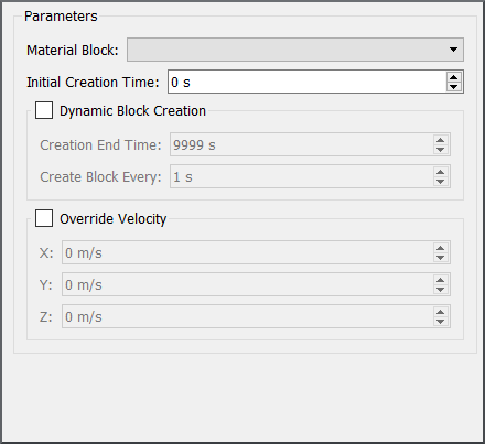
Material Block
The dropdown displays all the saved material blocks within the Material Database that have been transferred to the current simulation deck. Transferring a block from the Material Database to the current simulation also transfers all the relevant Bulk and Equipment materials, interactions, and the Contact Model used.
-
Without choosing any additional settings, EDEM will place as many copies of the selected block as they fit within the volume of the factory box. This will essentially create a bed of material within the box domain.
-
If Dynamic Block Creation is selected, EDEM will perform the above action every time you set a period in the Create Block Every section. If the geometry box is the same size as the original saved block, then one block will be created every time period, essentially taking the output of one simulation as an input to another.
-
If Override Velocity is selected, EDEM will overwrite the stored material velocity with the user-specified value.
EDEM will place as many copies of the selected block as they fit within the volume of the factory box.
Selecting Geometry Sections Parts
You can select Geometry sections by clicking on the required geometry in the Viewer window. The geometry in the Creator Tree is highlighted.
You can select multiple geometries in the Creator Tree by expanding the Tree and holding down the Ctrl key while selecting the geometries. The advantage of this method is that once multiple Geometries are selected, the Material can be changed or assigned for all selected Geometries using the General > Material option. Alternatively, you can delete multiple geometries using the Delete key or the  icon.
icon.
Using the Volume Packing Tool
The Volume Packing tool is used to fill a geometry with particles based on a user defined solid fraction. The process of achieving this is to generate the required number of particles to satisfy the solid fraction and then iteratively rearrange the particles to remove overlaps between the overlapped particles and particles overlapping the geometry. There are two different methods available for the volume packing tool. The first one (recommended), is based on calculating particle displacement based on the average distance to neighboring particles. The second one is an optimization algorithm that calculates the displacement by solving an optimization function based on the total distance to particle neighbors and geometry.
Volume packing is calculated at the start of a simulation, but the creation of the material can be offset to the required start time within the simulation.
To use volume packing:
- Select a closed volume from the Geometries tree.
- Right-click Add volume packing.
- Define the materials to fill the volume, which can be a mix of different materials.
- Select the appropriate Solid fraction (0.7 would be very high, 0.4 would be very low)
NOTE
The volume packing tool does not calculate forces based on overlaps, creating material with very high overlaps could lead to a particle explosion once the forces are calculated in the physics model. - Set the start time which is the time where the particles will enter the simulation.
- For further configuration of the volume packing tool, click the cog icon.
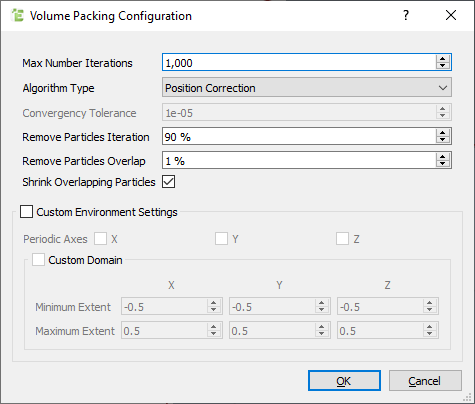
|
Max Number Iterations |
Maximum number of iterations for the generation |
|
Algorithm Type |
|
|
Convergency tolerance |
Used in the optimization algorithm to determine when the bed is fully settled. |
| Remove Particle Iteration | Set the start iteration for applying filter. This is expressed as a percentage of the Max Number of Iterations. |
| Remove Particle Overlap | Criteria to remove particles by overlap. Value representing a fraction of particle’s radius. |
| Shrink Overlapping Particles | After exiting the main loop, reduce the particle size to remove any remaining overlap |
| Periodic Axes | Define the axis which are periodic (see periodic boundaries) to generate material blocks. |
Using Filters
Filters are used to remove particles with large overlaps. The filter is applied after a certain number of iterations and the size of the overlap is user defined.