| 1. | On the Boundary Conditions section of the Utility Menu, click Create/Edit BC. |
| 2. | The Create/Edit Altair HyperXtrude Boundary Conditions dialog opens. Click BCs to create a new boundary condition. |
| 3. | On the right side of the panel you will see the current boundary condition. Edit this panel to set the following conditions. |
| • | Material: Leave the default as it is |
| 4. | Select a color of your choice for the BC. |
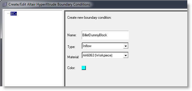
| 5. | Click Create to set the parameters for this BC. Set the following data and leave the rest to default values. |
| • | Temperature = 800.0 deg F |
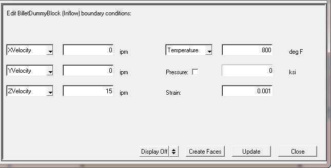
| 6. | Click Update to save this data. |
Note: For the BilletDummyBlock BC (inflow), your extrusion velocity (Z velocity in this example) will have to be identical to your Process data - Parameters - Metal Extrusion - Ram Speed. You will evaluate process data later in this tutorial.
In the following steps, you will assign elements into the dummy_block boundary condition you just created.
| 7. | Click the XY Bottom Plane View icon  on the toolbar to change the graphics view. on the toolbar to change the graphics view. |
| 8. | Click Create Faces to prepare assigning BC face elements for this BC. |
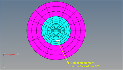
| 9. | With the blue halo surrounding the elem button, select the boundary elements by selecting one of the interior elements on the Inflow face with the left mouse button. |
| 10. | Click proceed to create BC faces and assign it to this BC. |
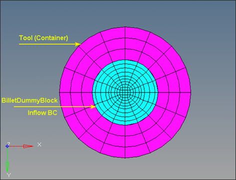
| 11. | When you are finished, notice that the BilletDummyBlock regions are identified and face elements are created and assigned to the BilletDummyBlock_BC. |
| 12. | Click on the Model Browser and notice a new component, DummyBlock_BC, is created. |
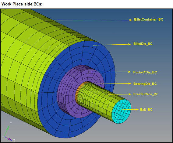
| 13. | Next, you will create the BilletContainer BC. This BC represents the Billet surface that is in contact with the Container. Click on BCs in the Create/Edit Altair HyperXtrude Boundary Conditions window. |
| 14. | Set the Name of the BC as BilletContainer; Type as SolidFluidInterface and accept the default material (Workpiece material). Choose a color and click Create. |
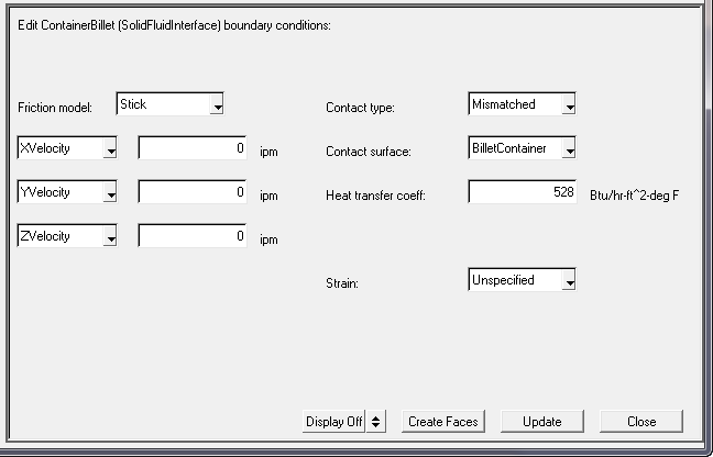
| 15. | Under Edit BilletContainer (SolidFluidInterface) boundary conditions:, accept the default values for the Friction model and XVelocity, YVelocity, ZVelocity and Strain. |
| 16. | Select Mismatched for Contact type. |
| 17. | Set the value of 528 for Heat transfer coeff. You will set the Contact surface little later. |
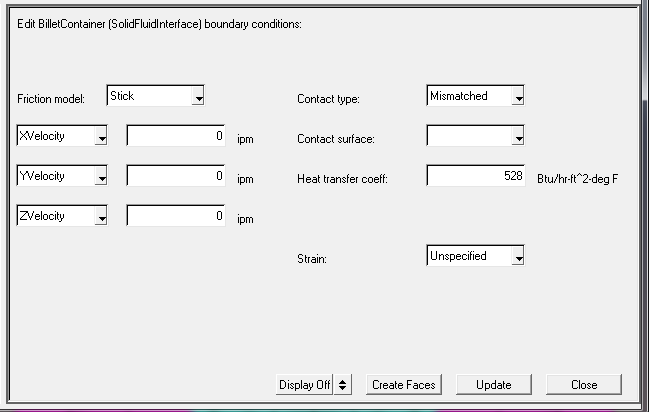
| 18. | Click Update and click on Create Faces. |
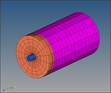
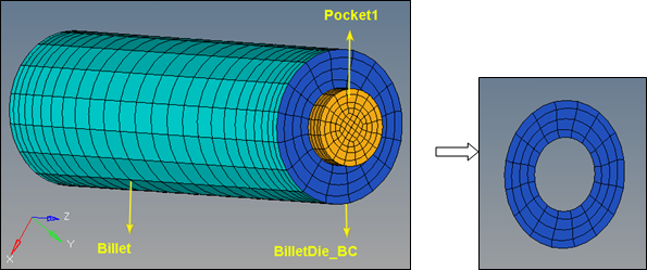
| 19. | Display only the Billet in the graphics area. Select an element on the Billet surface as shown in the figure below. |
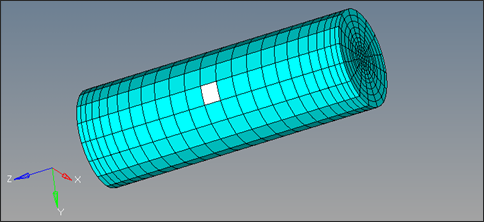
| 20. | Click on elems >> by face and click proceed. This will create the face elements for BilletContainer BC. |
| 21. | Similarly, create the ContainerBillet BC with the attributes |
Name: ContainerBillet
Type: SolidFluidInterface
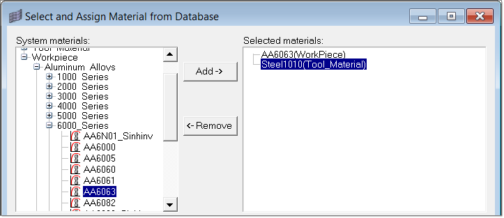
Material: H_13(Tool)
| 22. | Choose a color and click Create. |
| 23. | Under Edit BilletContainer (SolidFluidInterface) boundary conditions:, accept the default values for the Friction model and XVelocity, YVelocity, ZVelocity and Strain. |
| 24. | Select Mismatched for Contact type and set the value of 528 for Heat transfer coeff:. |
| 25. | Set the Contact surface to BilletContainer from the dropdown menu. |
| 26. | Click Update and click on Create Faces. |
| 27. | Display only the Container in the graphics area. Select an element on the Container inner surface as shown in the figure below. This will create the face elements for ContainerBillet BC. |
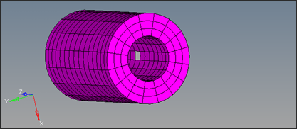
| 28. | Click on elems >> by face and click proceed. |
| 29. | Now click on the BilletContainer under BCs and set the Contact surface as the ContainerBillet using the drop down menu. |
| 30. | Similarly create all other BCs with attributes and the data as detailed below |
| Note: | If the Contact Surface required for the BC data is not available under the Contact Surface drop down, you have not yet created it. Work through the table in the order provided, going back and adding the Contact Surfaces as you create them. |
Region
|
BC name
|
BC Type
|
BC Data
|
Billet - Die Contact Surface on the Billet
|
BilletDie
|
SolidFluidInterface
|
Friction = Stick
X, Y, Z Velocity = 0
Contact Type = Mismatched
Contact Surface = DieBillet
Heat Transfer Coeff = 528
Strain = Unspecified
|
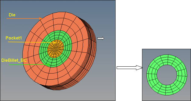
Billet - Die Contact Surface on the Die
|
DieBillet
|
SolidFluidInterface
|
Friction = Stick
X, Y, Z Velocity = 0
Contact Type = Mismatched
Contact Surface = BilletDie
Heat Transfer Coeff = 528
Strain = Unspecified
|
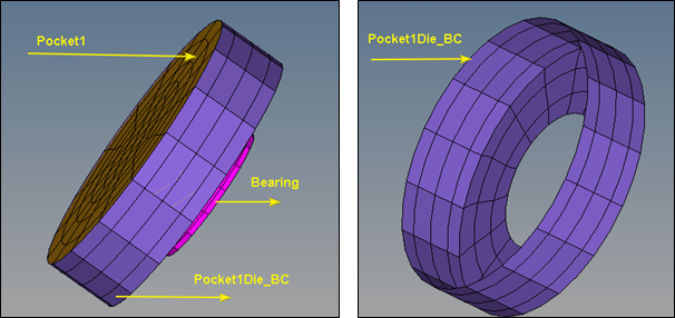
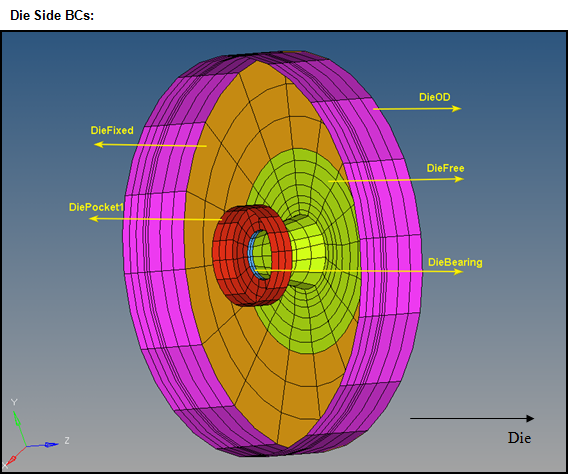
Pocket1 - Die Contact Surface on Pocket1
|
Pocket1Die
|
SolidFluidInterface
|
Friction = Stick
X, Y, Z Velocity = 0
Contact Type = Mismatched
Contact Surface = DiePocket1
Heat Transfer Coeff = 528
Strain = Unspecified
|
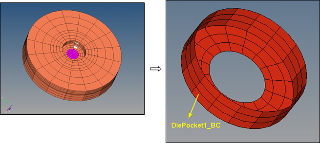
Pocket1 - Die Contact Surface on the Die
|
DiePocket1
|
SolidFluidInterface
|
Friction = Stick
X, Y, Z Velocity = 0
Contact Type = Mismatched
Contact Surface = Pocket1Die
Heat Transfer Coeff = 528
Strain = Unspecified
|
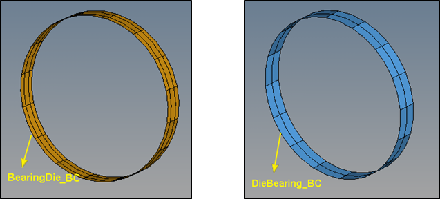
Bearing - Die contact surface on the bearing (extracted from “Bearing3D component” )
|
BearingDie
|
SolidFluidInterface
|
Friction model = Viscoplastic
Friction coeff = 0.3
Slip Velocity X, Y, Z = 0
Contact Type = Mismatched
Contact Surface = DieBearing
Heat Transfer Coeff = 528
Strain = Unspecified
|
Bearing - Die contact surface on the Die (extracted from “Die3D component” )
|
DieBearing
|
SolidFluidInterface
|
Friction model = Viscoplastic
Friction coeff = 0.3
Slip Velocity X, Y, Z = 0
Contact Type = Mismatched
Contact Surface = BearingDie
Heat Transfer Coeff = 528
Strain = Unspecified
|
Profile Surface
|
FreeSurface
|
FreeSurface
|
Heat transfer type = Heat Flux
Heat flux = 0
|
Profile Exit
|
Exit
|
Outflow
|
X, Y, Z Traction = 0
HeatFlux = 0
Pressure is checked and 0
|
Container Outer Diameter
|
ContainerOD
|
ToolSurface
|
X, Y, Z displacement = 0
Heat Transfer type = Heat flux
Heat flux = 0
|
Die Outer Diameter
|
DieOD
|
ToolSurface
|
X, Y, Z displacement = 0
Heat Transfer type = Heat flux
Heat flux = 0
|
Die exposed region (with Radius > 4) facing + Z direction
|
DieFixed
|
ToolSurface
|
X, Y, Z displacement = 0
Heat Transfer type = Heat flux
Heat flux = 0
|
Die remaining
|
DieFree
|
ToolSurface
|
X, Y, Z traction = 0
Heat Transfer type = Heat flux
HeatFlux = 0
|
Container Back
|
ContainerBack
|
ToolSurface
|
X, Y, Z displacement = 0
Heat Transfer type = Heat flux
Heat flux = 0
|
Note:
| a) | If you are in doubt about any of the BCs, look at the completed model at the same location. |
| b) | Mismatch interface indicates the common boundaries between Tool and Workpiece are different. |
| c) | Nodes are not equivalenced between two different mismatched interfaces. |
| d) | Mismatched interface can be used for both Steady State and Transient analysis. |
| e) | You must specify boundary conditions over elements on both sides of the contact surfaces (Two BC components). |
| f) | When ToolSurface specified with X,Y,Z displacement = 0, you are defining that the associated tool location is fixed. When X, Y, Z traction = 0 is specified, you allow the Tool to freely move. |
| g) | You can also use Face panel to extract 2D face elements from solid elements, then assign to different boundary BC component individually. |
| h) | In this tutorial, the BC attributes are the same in both DieOD and DieFixed BC components. An alternative method is to combine both BC components and create only one BC component. |
| i) | SolidFluid interface enables materials to slip. This BC type has multiple slip models, such as coulomb friction, slip velocity, etc. When the SolidFluid interface is set, heat transfer is applied. If meshes are joined, the solver calculates the heat transfer automatically. If not, the heat transfer needs to be manually specified and the heat transfer coefficient is defined by the user. |
|