Two options are available to translate nodes. Both begin by selecting the Translation window ( ) sub-window.
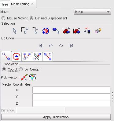
Method 1: Define a vector
| 1. | Click the Coord. toggle to activate it. |
| 2. | Define a vector by using one of the following: |
| • | Click  and, in the graphic window, click the two nodes defining the vector. and, in the graphic window, click the two nodes defining the vector. |
or
| • | Click  and in the graphic window, pick three nodes to define a plane, and by extension its normal vector. and in the graphic window, pick three nodes to define a plane, and by extension its normal vector. |
or
| • | Fill in the Vector Coordinates: X, Y, Z fields and click Apply Translation. |
| 3. | Once the vector is defined, click Apply Translation as many times as necessary to repeat the same displacement. |
| 4. | If necessary, click the functions to undo or redo the displacement. |
| 5. | Click Close to close the menu. |
Method 2: Define a direction and a distance
| 1. | Click the Dir./Length toggle to activate it. |
| 2. | Define a direction by using one of the following: |
| • | Click and in the graphic window, click the two nodes defining the direction. |
or
| • | Click and in the graphic window, pick three nodes. |
or
| • | Fill in the Vector Direction: X, Y, Z fields. |
| 3. | In the Distance field, set the translation distance. |
| 4. | Once the vector is defined, click Apply Translation as many times as necessary to repeat the same displacement. |
| 5. | If necessary, click the functions to undo or redo the displacement. |
| 6. | Click Close to close the menu. |
Go to
Move


