Die Compensation |

|

|

|

|
|
Die Compensation |

|

|

|

|
The Die Compensation tool enables positioning of the springback part relative to the reference part, and compensates the die for springback.
On the Tools menu, click Die Compensation. The Die Compensation panel opens to the Import tab:

The following fields are available for file selection on the Import tab:
Field |
Description |
Reference Model |
This is the part file after forming: RADIOSS STA file or LS-DYNA dynain file. |
Deformed Model |
This is the part file after springback: RADIOSS STA file or LS-DYNA dynain file. |
Die |
This is the die file that was used for forming the reference model. The die file should include mesh, but geometry is optional. |
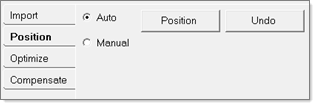
This tab includes options for Auto and Manual positioning.
| 1. | Select Auto to auto-position a springback part onto a reference part if the mesh for the reference part and springback part are identical. |

| 2. | Select Manual to manually position the springback part, and then enter values for rotation and translation. |

This tab lets you optimally position the springback part to the reference part such that the selected nodes on the springback part have minimum or no deviation from the reference part. You can pick the nodes on the springback part, and then set the limits for translation and rotation.

| 1. | Select the components for the blank (reference part) and die. Set the Blank thickness value for offset purposes. |
| 2. | Click Offset to offset the deformed part and reference part by half of the blank thickness to match with the die surface. |
| 3. | Click Compensate Mesh to compensate the die mesh for the differences between the reference model and deformed model. |

| 4. | Click Compensate Geometry to update the die surface. |
| 5. | When finished, select Close to close the Die Compensation dialog. |