Guidelines for Non-Hex Meshes
| 1. | Die exit (Profile): Place four free nodes between the opposite walls (profile thickness). Same guidelines apply for steady and transient analysis. |
| 2. | Bearing Region: Use a constant element length in the flow direction. General rule is to use four elements to represent smallest bearing length. This allows the program to predict accurately flow at the die exit |
| 3. | Profile section: Length of the profile section should be approximately: |
| - | 10 times the maximum bearing length |
| • | Transient moving analysis: |
| - | 3-5 times the maximum bearing length |
| • | The size the mesh in the Profile3D region could become large; by using biasing options in drag, you can try to reduce it. |
| 4. | Use triangular prism (Penta6) in the bearing and profile regions |
Mesh Generation Steps
| 1. | Create solid volumes of different components (billet, portholes, weld chamber, bearing, backer, bolsters, mandrel, etc.) |
| 2. | Using the Extrusion Wizard is the fastest and simplest approach to creating a mesh. However, if your model needs manual meshing due to complexity, then create the bearing and profile with Penta6 elements and the rest using Tet4 elements. The bearing region can be meshed either using the drag or solidmap options. Profile regions are created using the drag option from the faces of the bearing3D mesh. Use the volume tet meshing option to create a tet4 mesh in the rest of the components. |
| 3. | Start with the bearing region first. Next, generate mesh in other components - weld chamber, portholes, billet, etc) This allows you to create meshes with small element size in regions close to the die exit |
| 4. | Try to ensure that the elements meet the following criteria: |
| • | Max. aspect ratio: TET4 < 8, PENTA6 <15, PYRAMID5 < 12 ; HEX8 <25 |
| • | Min. value for “tet collapse” for elements in portholes and weld chamber is > 0.2 |
Mesh for Tool Geometry
| 1. | It is preferred that the mesh at the interface of the tool and workpiece is not connected. This is denoted as mismatched in the interface. This is a must for transient analysis at the Billet - Container and Billet - Die interface. |
| 2. | It is also preferred that the mesh at the interface is nearly identical in size, even though they are mismatched. This will greatly improve the contact searches and accuracy. However, if you are unable to maintain this same mesh size of the Container3D side, you can have twice or three times coarser than the workpiece mesh. |
| 3. | The Extrusion Wizard creates the tool mesh with identical boundary mesh at the interface and then disconnects the tool and workpiece meshes. If you are manually meshing the model, we recommend this strategy. |
Other Meshing Guidelines
Element Density (No. of node/dofs)
| • | Place an adequate number of elements in the flow path. This is essential to capture the flow and avoid choking. |
| • | In a typical cross-section of the profile or extruded part, place 4 to 5 elements (linear) across each section. |
Element Quality
| • | When the mesh contains higher order elements (HEX20/HEX27), make sure that the element Jacobian (in HyperMesh or your mesh generator) is greater than 0.4. Also notes that higher order elements are supported only for HEX elements. |
| • | Even though it is not necessary for HEX8 (linear elements), the same guideline is still recommended. |
| • | Mid nodes on the sides/face of an higher order element should be preferably placed at the mid-point between (or closer to this) the corner node. If not, this will affect the Jacobian computations inside HyperXtrude. |
Checks for Errors
Before exporting the data from the HyperXtrude user profile, check for:
| • | Duplicate nodes/elements |
| • | If it is a 2D or axisymmetric problem, make sure the normal point to +ve Z axis 95% of the errors made in HyperXtrude data decks are incorrect data in BCs and process parameters. Double-checking your values for consistency will save you time. |
General Tips
| • | If you are using a hexahedral mesh: |
| - | Element Jacobian should be greater than 0.4 for higher order elements |
| - | You cannot mix HEX8 and HEX20 elements in the model |
| - | If you want a coarser mesh, use HEX20 elements, to capture the curved geometry |
| • | For axisymmetric analyses, use second-order elements (QUAD8 or QUAD9). |
| • | Non-QUAD elements are NOT supported for 2D and axisymmetric analysis. |
| • | Around die exit, element aspect ratios should be close to 1.0 (good transition) |
Guidelines for Mismatched Mesh
Generally, two guidelines should be followed when building a mismatched mesh between the tool and the workpiece:
| • | The ratio should be less than 1:20 for HEX mesh. That is, one coarse element on the tool side should not be in contact with more than 20 elements on the workpiece side. For a tet mesh, nearly identical mesh at the interface is preferred. |
| • | Mesh on either side should be fine enough to follow the curvature. |
Typically, a model has large curvature in only one plane, as dictated by the profile geometry. Try to follow the curvature on that plane; the mesh can always be coarsened in the extrusion direction (typically Z), along which the mesh is dragged.
The following examples demonstrate mismatch ratios, curvature tolerances, and overlap.
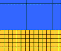
Example 1: Acceptable Mismatch Ratio
The following mesh is good because for every element on the tool side, there are about 6 to 7 elements on the workpiece side, which is an acceptable ratio.
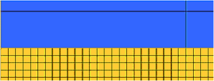
Example 2: High Mismatch Ratio
The following mesh shows more than 20 elements on the workpiece side for every element on the tool side. This ratio is unacceptable and will lead to incorrect results.
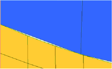
Example 3: Acceptable Curvature Tolerance
In the following mesh, a crack exists between the tool and the workpiece elements. The tool elements do not follow the curvature. If the gap is less than 2.5 percent of the element size on the workpiece at the center of the face, the mesh is acceptable and the gap between the elements is within the tolerable limits.
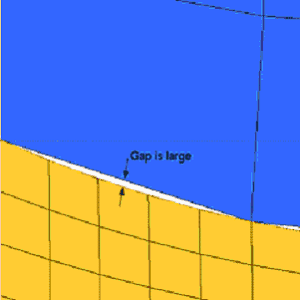
Example 4: Unacceptable Curvature Tolerance
In the following mesh, a large crack exists between the tool and workpiece elements. The tool elements do not follow the curvature. Some of the workpiece elements will not correctly identify the tool element, leading to incorrect results.
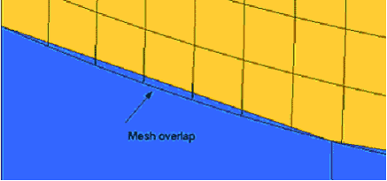
Example 5: Acceptable Overlap
Depending on the curvature of the model, tool elements might overlap the workpiece elements. Overlap is acceptable when the overlap does not extend past one full element. Even if the overlap extends beyond one element, element detection is not affected. Only the accuracy of the results is impacted.
Return to Metal Extrusion Tutorials


