The Blank Shape tool lets you view and write out an IGES data file of the initial blank profile. The tool also predicts the minimum blank shape needed to form a simulated part.
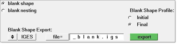
Select Tools > Blank Shape, and the following dialog opens:
Blank Nesting
The Blank Shape tool includes the option for Blank Nesting.
| • | Select the blank nesting radio button, and then pick the line in the model that corresponds to the blank’s outline. |
| • | Click nesting. The blank nesting dialog opens for you to modify the blank positioning as needed to optimize the material usage. |
How do I...
| 1. | Click file = and then select a file to display. |
| 2. | Select Initial to display the minimal blank shape. |
| 3. | Select Final to display the part geometry. |
|
| 1. | Click file = and select a file to display. |
| 2. | Select Initial to display the minimal blank shape. |
| 3. | Click filename = and type the name of the IGES file. |
| 4. | Click write to output the IGES file for the blank profile. |
|
See also
Tools
Blank Nesting


