Manufacturing Solutions

HF-0150: Quick Setup

HF-0150: Quick Setup

Previous topic Next topic Expand/collapse all hidden text  

HF-0150: Quick Setup

Previous topic Next topic JavaScript is required for expanding text JavaScript is required for the print function  

This tutorial shows you how to set up and run a one-step analysis from the RADIOSS One Step user profile.


Files for this Tutorial

part1a.igs


hmtoggle_arrow1greyExercise 1: Geometry Cleanup and Meshing

Step 1: Load the model file

1.Launch HyperForm with the RADIOSS One Step user profile.
2.Click File > Import > Geometry.
3.Click the Select Files icon fileOpen-24and navigate to part1a.igs.

Note: The model files for this tutorial are located in the file mfs-1.zip in the subdirectory \hf\1Step\. See Accessing Model Files.


4.Click Import, and then click Close.

import_panel_geometry_option

The model loads and looks something like this:

model_one_step_part1a.igs

Step 2: Geometry cleanup

1.Select the OneStep tab, right-click Parts, and then select New > Pick:

HF_0150_02

Note: The component name is recognized automatically as Part once the model is loaded into the session.

2.Pick the part from the screen.
3.Click proceed.

The default material, CRDQ steel with 1 mm thickness, is assigned to the part.

4.On the tree under Parts, right-click lvl1, and select Geometry > Remove Holes.

HF_0150_03

5.In the field diameter<, enter 40.
6.Click the yellow surfs button. The button highlights to show that it is activated. Click surfs again and from the extended entity selection menu, select displayed.

All of the entities on the model are selected.

7.Click find.

All pinholes found are highlighted with xP.

8.To close the hole, click delete.
9.To close the panel, click return.

Step 3: Meshing the part

1.On the tree, under Parts, right-click lvl1, and select Mesh > R-Mesh.
2.Enter these values:

HF_0150_07  

3.Click Mesh.
4.Click Close.


hmtoggle_arrow1greyExercise 2: Setting up the One Step Analysis

Step 1: Assigning the material and thickness to the part

1.To change the material, on the tree, under Parts, right-click CRDQ Steel > Database.

Note: You can add a user-defined material to the database by editing the material file hf.dat.

2.When finished modifying the material selection, click Close.
3.On the tree, under Parts, select Thickness:1; on the digit 1, double-click to edit, and enter 1.5.

Step 2: Setting symmetry conditions

On the tree, under Settings, right-click Symmetry:No, and select + X.

Step 3: Setting the stamping direction

On the tree, under Settings, right-click Stamping Direction, and select Z.

Note: In the Autotip panel, the vector selector switch lets you assign a direction. If the stamping direction of the part is not one of the principal axes, do the following: select the option N1, N2, N3; select two nodes on the model; and click set.

Step 4: Selecting the blankholder

Blankholders can be defined as the upper and lower holding surfaces that control metal flow around a shape to be formed in a draw operation. They supply a restraining force on the material during the pressing process.

HyperForm lets you to define the blankholder force in two ways: on element or edge. The correlation between the magnitude and level of the applied forces is always available. Edge blankholder force application allows you to restrain an edge by enabling automatic selection of all nodes between two user-defined nodes along a free edge of a part.

You can define the blankholder force in two ways: tonnage force or pressure level (high, medium and low).

Note:The pressure level is proportional to the area of blank under the blankholder as well as thickness. A pressure level of 2MPa, 5MPa and 10MPa for a 1mm blank has been chosen as a reference for Low, Medium, and High (based on practical experience). The tonnage (metric ton unit) is equivalent to the pressure times the blankholder area normalized/scaled by the thickness (1 metric ton = 9810N).


1.On the OneStep tab, right-click Blankholders > New. If desired, you can double-click on Blankholder1 to change the name.
2.Right-click Blankholder1 > Elements…
3.Click elems and select on plane.
4.Select z-axis and pick a node on the binder (flat region) for B (base node).
5.Click proceed.

Nodes for Friction, Tonnage and Pressure appear below Blankholder1.

6.Double-click the values for Friction and Tonnage to change the values.
7.Right-click Pressure Level, and select Medium.

Notice that the Tonnage changes according to the selected pressure level.

Step 5: Creating drawbeads

Modeling the exact drawbead geometry requires a large number of elements, which increases CPU time dramatically. A practical approach is to use an equivalent drawbead model by representing the drawbead analytically and providing a constant drawbead restraining force and closure force.

Use the calculate subpanel to determine the closure and restraining force based on drawbead dimensions. The restraining force is the value of the force (per unit length) applied by the bead in the plane of the blank surface. The closure force is the force (per unit length) required in the perpendicular direction to keep the drawbead closed.
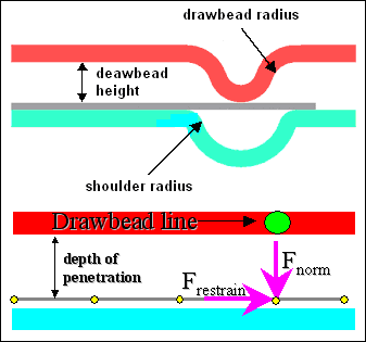
HF_0150_08

1.From OneStep tab, right-click Drawbeads > New > Restrain… .
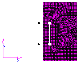
2.To define the drawbeads, pick two nodes on the part as you see in the following image:

HF_0150_09

3.Click Proceed, and the following message is displayed: The drawbead set has been created.

A line representing drawbeads is created.

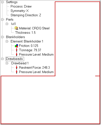
4.Notice that Drawbead1 is created with a default Restraint Force and Pressure Level. Double-click Drawbead1 to rename it.
5.Right-click Pressure Level > Medium. Notice that Restraint Force changes based on the Pressure Level selection.

Step 6: Tipping

1.Right-click the OneStep tab anywhere in the red box as you see below, and select Autotip.

HF_0150_10

2.In the panel, select the autotip radio button.
3.Verify the entity selector is set to comps and select the lvl1 component.
4.Verify the toggle is set to full model and keep the rest of the options as default.
5.Click calc autotip.

The angle to be tilted is displayed on the header bar on the left hand bottom corner and the magnitude is displayed in the angle field.

6.Click autotip.

This action tilts the part by an angle calculated by HyperForm to reduce draw depth during forming.

7.Click return.

Step 7:  Checking for undercuts

1.Right-click the OneStep tab anywhere in the red box as above, and select Undercut Check.
2.Click the yellow comps button to highlight it.
3.Pick the part from the screen.
4.Click check undercut.

Notice the message “0 elements with undercut detected.” If undercuts are present, then the failed elements are highlighted in the model.

5.Click return.

Step 8:  Checking the model and running the analysis

1.Right-click the OneStep tab anywhere in the red box as shown above, and select Check Model.

A message is displayed on the message bar, stating “Model checked.”

2.Right-click the OneStep tab, and select Run.
3.Enter a name for the run. The feasibility solver launches.

Note: It is recommended to specify a unique directory for the analysis.


hmtoggle_arrow1greyExercise 3: Post processing

After the successful completion of the run, right-click the white space of the OneStep tab to see the Blank Shape, %thinning and Formability options, which were not available before running the analysis.

HF_0150_12

Right-click and select the desired result type for post-processing.

Step 1: Blank Shape

1.Right-click the OneStep tab anywhere in the white space and select Blank Shape.
2.Under Blank Shape Profile: click Initial. Notice that the initial blank shape is displayed on the screen, as shown below.

HF_0150_13

3.Click export to write out an iges boundary of the predicted blank shape to the folder where feasibility analysis was run. The file is named <filename>_blank.iges.


hmtoggle_arrow1greyExercise 4: Blank Fit

Step 1: Fitting the initial blank shape into different configurations

1.From the Tools menu, click Blank Fit.

The blank fit utility options are displayed:

HF_0150_14

2.Use the Part drop down menu to select the component on which the one step analysis was run.
3.Keep the default values for Density and Cost per Kg.
4.Under PLOT OPTIONS, click the checkbox next to %Thinning and Formability.  Notice that %Thinning and Formability buttons becomes active.
5.Rotate the model to a desired direction and click %Thinning. This contours the model with %Thinning result type.
6.Left-click to capture the image to include it in the report. A right-click will abort the function and return to the Blank Fit macro. This is indicated by the image on the right hand bottom corner of the graphics area .
7.Under BLANK SHAPES, check all the boxes.
8.Click Blank Fit.

The blank is fit into the selected shapes.

9.Click Publish Report.

This opens an HTML report with hyperlinks to blank shapes and results:

HF_0150_15

11.Click Close.


hmtoggle_arrow1greyExercise 5: Blank Nest

Step 1: Nesting the initial blank shape on coil or sheet

1.Click Tools > Blank Nesting.
2.From the panel, click elems > displayed.
3.Click nesting.

The Blank Nesting window appears with options to nest the blank in different configurations.

HF_0150_16

4.For nesting setup, select Coil.
5.To quickly obtain the nesting pattern for the coil, in the tool bar, select the one-up tool: icon_one_up.
6.Click File > Export.
7.Enter a name, and click Save.

An .iges boundary of the nested sheet is saved.

8.To close the Blank Nesting window, select File > Exit.

Note: For more information see, Blank Nesting.


hmtoggle_arrow1greyExercise 6: Report Generation

Step 1: Publishing a report of the feasibility analysis results

1.Click Tools > Report Generator.

The Report Generator appears:

HF_0150_17

2.Click the Result File: file browser icon and select <filename>.res in the folder where you have run the feasibility analysis.

Note: You must run feasibility analysis in a separate folder with no spaces in the path and in the folder name.

3.Click the Report Name: file browser icon and type a name for the report. The folder and report name must not have any spaces in the folder name or file name.
4.Check all the boxes under Result Types.
5.Under Export Mode, select HTML.
6.Under Export Options, select JPEG.
7.Click Generate. This creates a report in the folder selected in the Report Name field. It includes folders called <filename>_data_dir and <filename>.hml.
8.Open the folder that was selected for Report Name. Open the file <filename>.html in Internet Explorer or Firefox. This opens a html page with hyperlinks to the selected result types and the corresponding image with contour, as shown below:

HF_0150_18

9.Click Close to close the panel.