offset subpanel |

|

|

|

|
|
offset subpanel |

|

|

|

|
This subpanel can be used to offset a group of surfaces by a given distance along the normals of those surfaces. A negative offset value can be used to offset these surfaces in the opposite direction of the surface normal. The topology of the surface edges (free, shared edges, and so on) is maintained during the offset function. Some individual surfaces will be trimmed or extended to maintain the connectivity. This function moves the selected surfaces to the new location.
If you want to save the original surfaces, the selected surfaces can be duplicated (using the extended entity selected popup window) before the offset. You can review the normal direction of the surfaces by clicking vector normal or color normal. If the offset direction is incorrect, the reverse normal function can be used to reverse the normal of a selected surface. If there are elements associated to the offset surfaces, the element will not move along with surfaces. The association between the elements and their surfaces is broken.
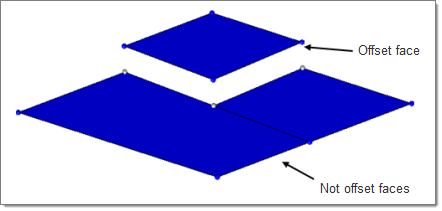
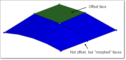
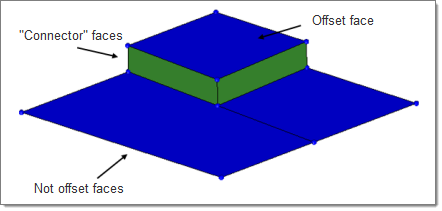
There are two major types of offset: disjointed and continuous. Disjointed offsets move the selected surfaces without retaining their connections to surrounding geometry, while continuous ones will either morph surrounding geometry to maintain connectivity, or create new surfaces to do so.

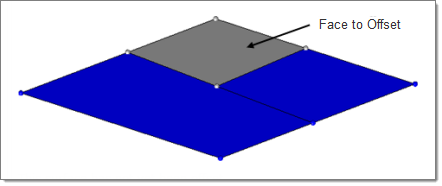
This surface has not yet been offset.

This is a disjointed offset.

This offset uses the "continuous" option.

This offset uses the "continuous" option, with separator lines specified at the edges of the offset surface.
Input |
Action |
||
disjoint offset / continuous offset |
A disjoint offset simply moves the surface, completely breaking its continuity with anything that it might previously have been in contact with. A continuous offset creates new surfaces to connect the surface at its new position with lines that you specify, or morphs any surrounding/attached surfaces to meet the offset surface if no separator lines are chosen. |
||
update eccentricity |
This value is stored internally, and can be used later by the Midsurface Thickness Map utility. It will not affect the movement of the offset surface; instead, the surface's associated thickness and offset values will remain in its original location, but be given values relative to its new location. Later, these values can be used in the midsurface thickness utility to map its thickness and offset to FE elements. |
||
remove degenerations |
Degenerations are surfaces that become collapsed or unnecessary as a result of the offset. |
||
autocomplete separators |
This option automatically selects all segments of a closed loop of lines when you select any single line within the segment. |
||
surfs selector |
Select the surface to offset. |
||
separator lines: lines selector |
Indicate where the offset surface should remain attached; new surfaces will be generated to keep the surface continuous. |
||
offset = |
This can be a positive or negative number. If you are uncertain where the positive normal direction lies, use the vector normal or color normal buttons to display it, and reverse normal if necessary/desired.
|