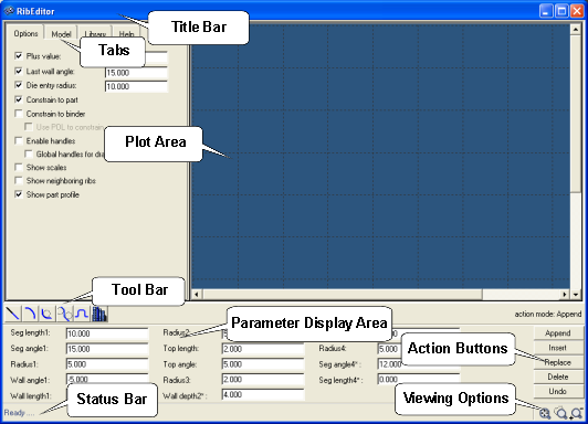
The Rib Editor is a two-dimensional GUI for designing parametric cross-sections of an addendum. These cross sections are known as ribs. Ribs can be constructed from one or multiple basic shapes, known as segments. After designing ribs, you can add them to a model, and later use them to create an addendum surface.
The major functions of the Rib Editor include:
Options Tab
Includes a variety of display, constrain and editing options:
Plus value
|
A straight line section added to the edge of a part. Default=10 mm.
|
Last wall angle
|
Section wall angle. Default=15 degrees.
|
Die entry radius
|
Default=10 mm.
|
Note: When the plus value, last wall angle and die entry radius are enabled, you activate the global values. Any appended rib segments use the activated values as default. For example, if you activate a plus length value = 10.0, any new plus line segments added in the Rib Editor will have the value of a straight segment with the default value = 10.0.
|
Constraint to part
|
Constrains the rib so that it is tangent with respect to the edge of the part.
|
Constrain to binder
|
Constrains the rib so that it is tangent with respect to the edge of the Binder.
|
Enable handles
|
Creates a center for the curved portion of the ribs on the graphics screen for changing the curvature value (left-click + hold the yellow center button).
|
Show scales
|
Marks the graphics screen with scales.
|
Show neighboring ribs
|
Displays neighboring ribs, if present.
|
Show Part pProfile
|
Displays the profile of the part along with the rib being created.
|
Model Tab
Provides the total number, the names, and the parameters of the segments that constitute the current rib.
Library Tab
Loads a file containing pre-existing shapes. You can retrieve the different shapes from the library to construct a rib. You can also add new shapes to the library file. shapes can also be added to the library file.
Help Tab
Displays information about the RibEditor.
|
Graphics display area for the ribs. When undercut is detected in the draw wall, a red dashed line appears that highlights the limits of the wall with the undercut condition.
|
Append/Insert
|
Adds a rib at the end or start of an existing rib.
|
Replace
|
Replaces an existing rib with a new rib.
|
Delete
|
Deletes a rib.
|
Undo
|
Reverts to the previous action.
|
Note: The current action mode is displayed on the toolbar directly above the action buttons.
|
Icons represent four basic shapes and a library for constructing ribs:
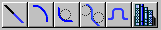
Plus
|
Adds a rib at the end or start of an existing rib.
|
Fillet
|
Replaces an existing rib with a new rib.
|
S-shape
|
Deletes a rib.
|
B-shape
|
Reverts to the previous action.
|
Library
|
Includes library of shapes.
|
| Note: | The parameters for the tool bar shapes can be changed in the parameter display area or by dragging and dropping control points from the options page. |
|
Located between the tool and status bars, the parameter display area lets you view and modify the parameters of shapes.
|
Located at the bottom of the Rib Editor window, the status bar displays messages concerning geometric constraints used during rib construction.
|
Zoom and fit tools are located in the lower right-hand corner of the window.
| • | To Zoom in/out, left or right click  , respectively. , respectively. |
| • | To zoom in on a circular area you select, click  . . |
| • | To fit the image, click  . . |
|
|
See also
addendum


