Exporting Data
Data collected during your simulation can be exported for analysis. Data can be exported from a single time step, a range of time steps, from all elements in your model or just from a selection or bin group.
Exporting data is carried out using queries. A query is used to define a single element attribute: For example, a query could be set up to extract the x-position of particles of type A in your model. Multiple queries can be grouped together under one Configuration ID and exported to a single file.
Creating a Configuration
Export data using the Export Data Dialog (File > Export > Results Data).
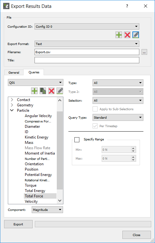
- Click on the + button to create a new Configuration ID. Multiple queries can be created within a single Configuration. In addition, multiple configurations can be created for any model: For example, one configuration may contain a number of queries relating to particles whilst another might have queries solely relating to contacts. Configurations can be edited at any point: for example, new queries added or redundant ones removed.
- Select the output file format: EnSight (.case) or Text (.csv). For EnSight files, be sure the total number of characters (filename and directory) is not more than 72.
- Give the configuration a title and enter a file name and location.
Export Data - General Settings
- Output Averages, Maximums, Minimums and Totals in Columns
This determines how data is laid out in the exported file. If this option is selected, data will be separated and extracted in unlabeled columns. The figures below both show a sample of some exported data. The data is the same in each case. In the first figure, the data is presented with this option not selected. The second figure shows it with the option selected.
Column Option Not Selected:
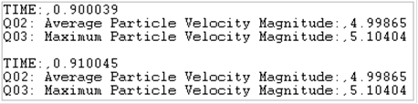
Column Option Selected:

- Output Domain
This option is only available when exporting data to an EnSight file. If selected, information on the domain will be exported with the data. If it is not, a new domain will be created automatically when the file is loaded in EnSight. - Delimiter and Line Break
If you are exporting to a text file, optionally change the delimiter to use and set whether to start a new line after X columns. By default, EDEM inserts a line break at 256 columns (the maximum allowable by Microsoft Excel). - Notation
Allows you to specify the notation used in your exported data files. Choose from:- Scientific (1.234567890 E08)
- Fixed-Point (123456789.0)
- Smart –switches from Fixed-point to Scientific at 1 E06 (or 1E-06)
- Precision
Specify the precision of the exported data files. This can be changed at the export stage, or in Tools -> Options -> Section Options -> Data Export Defaults, if you want to change the default for all subsequent exports. - Part Selection
This section is only active when exporting data to an EnSight file. Choose to export data on all elements in your model or just from specified ones. The elements are categorized by geometry sections and particle types. Information on contacts cannot be exported. Double click on any element to remove it from the group. Its listing will turn black indicating its exclusion. An element can be added into the list by double clicking on it a second time. - Time Steps
Data can be extracted from all time steps in your simulation or from a defined range. If a time step is from a partial save (indicated by the time step being grayed-out), data for the selected attributes may not be available. This is indicated by n/a in the exported file. A Step factor can be specified to extract data at a certain frequency despite the simulation deck containing more write-out points.
Export Data - Creating a Query
Queries define what information is exported. A configuration can contain multiple queries, each of which defines one data attribute.
The Query Tab:
Click on the Queries tab and click the + button to create a new query. The attributes that can be exported are listed under the element they relate to (collisions, contacts, particles or geometry). Click on any attribute to select it and then select the component of that attribute you are in interested in: for example the magnitude of a contact vector. All available attributes and their components are listed in the tables below.
Next choose the geometry section or type of particle or contact you want to export data for: for example choose only collisions between certain particle types, or the force on a particular geometry section.
Data can be extracted on all elements of the selected type (or geometry section) or it can be limited to just those contained within a particular bin group or selection group. This can be selected using the Selection drop-down list where all bin and selection groups that have been created are listed. Enable the Apply to Sub-Selections checkbox to export a separate query for each bin in a group (if defined), rather than one combined query for the entire group.
The Query Type option is used to determine which data values will be exported for a particular attribute: For example, if the query has been set up to export the velocity of particles of type A you could choose to export the maximum, minimum or average velocity per time step. The following data is exported for each query type:
- Standard. The value of the attribute for every element of the selected type for each time step in the defined range: For example, the velocity of every particle at each time step.
- Total. The sum of the values of the attribute for every element of the selected type: For example, the total velocity of all particles per time step. The total can be calculated per time step or over the range specified in the General settings section.
- Total Over Time. The sum of attribute values for every unique element over a period of time, repeated elements will not added to the total. For example, the total mass of particles to pass through a selection bin. If particles are within the bin on multiple write-outs the mass will still only be added once. Per Timestep switch will output a value for every write-out instead of just the final total.
Note: Particles must be within the bin for at least one write-out to be included in the total. Make sure the frequency of Write-out is small enough, or the bin is large enough to record every particle at least once. - Maximum. The maximum value of the attribute across all elements of the selected type for each time step in the defined range: For example, the maximum particle velocity per time step. The maximum can be calculated and exported per time step or over the range specified in the General settings section.
- Minimum. The minimum value of the attribute across all elements of the selected type for each time step in the defined range: For example, the minimum particle velocity per time step. The minimum can be calculated and exported per time step or over a specified range.
- Average. The average value of the attribute across all elements of the selected type for each time step in the defined range: For example, the average particle velocity per time step. The average can be calculated per time step or over a specified range.
- CoG. The value of the attribute at the Center of Gravity (CoG) of the geometry.
The final option is Specify Range. This is used to specify a value range for the data exported. In other words, limiting the export to data that falls between two specified values. For example, only exporting particle velocity data for particles traveling between 3m/s and 5m/s.
Further queries can be created in the same way. Once all queries have been set up, click the Export button to export your data to your specified file. Refer to Appendix A: Attribute Definitions for more information on attributes.
- * Queries are ordered using natural sort order where strings are ordered alphabetically except multi-digit numbers which are ordered as a single character.
Collision Elements:
Affects all or any combination of specific particles types or geometry sections.
| Attribute | Components | Query Type |
|
Average normal force. |
Magnitude, X, Y, Z. |
Standard, Avg., Total, Min. or Max. |
|
Average tangential force. |
Magnitude, X, Y, Z. |
Standard, Avg., Total, Min. or Max. |
|
Duration |
N/A |
Standard, Avg., Min. or Max. |
|
End time. |
N/A |
N/A |
|
ID |
N/A |
N/A |
|
ID Element n. |
N/A |
N/A |
|
Maximum normal force. |
Magnitude, X, Y, Z. |
Standard, Avg., Total, Min. or Max. |
|
Maximum tangential force. |
Magnitude, X, Y, Z. |
Standard, Avg., Total, Min. or Max. |
|
Normal energy loss. |
N/A |
Standard, Avg., Total, Min. or Max. |
|
Number of collisions. |
N/A |
N/A |
|
Position |
X, Y, Z. |
N/A |
|
Relative velocity. |
Magnitude, X, Y, Z. |
Standard, Avg., Total, Min. or Max. |
|
Relative velocity normal. |
Magnitude, X, Y, Z. |
Standard, Avg., Total, Min. or Max. |
|
Relative velocity tangential. |
Magnitude, X, Y, Z. |
Standard, Avg., Total, Min. or Max. |
|
Start time. |
N/A |
N/A |
|
Tangential energy loss. |
N/A |
Standard, Avg., Total, Min. or Max. |
|
Total energy loss. |
N/A |
Standard, Avg., Total, Min. or Max. |
|
Velocity of element A. |
Magnitude, X, Y, Z. |
Standard, Avg., Total, Min. or Max. |
|
Velocity of element B. |
Magnitude, X, Y, Z. |
Standard, Avg., Total, Min. or Max. |
Torque query standard, average, maximum or minimum will provide the torque values based on the individual triangular elements. The torque Specify Axis option is recommended or alternatively the torque Total via a specific axis:
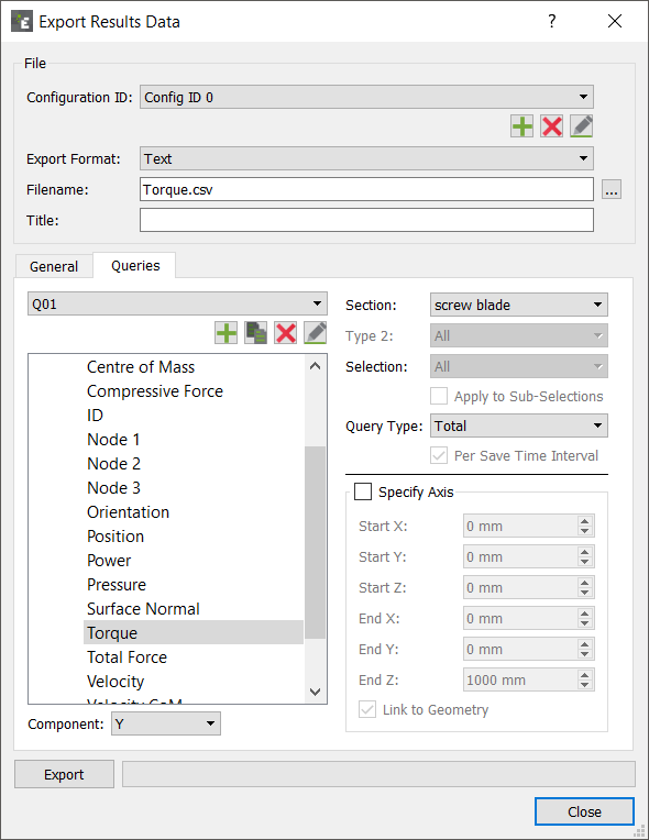
Torque Query Type Total Component X, Y or Z for a named geometry component (e.g. screw blade) will provide a resulting torque values along the X,Y or Z axis for the geometry component through the geometry Center of Mass.
The torque Specify Axis allows the user to determine which axis the torque is exported around, especially useful for geometry that is not aligned along the X,Y or Z axis or if the Center of Mass is not known. For example the auger in the image below has a rotation specified as shown:
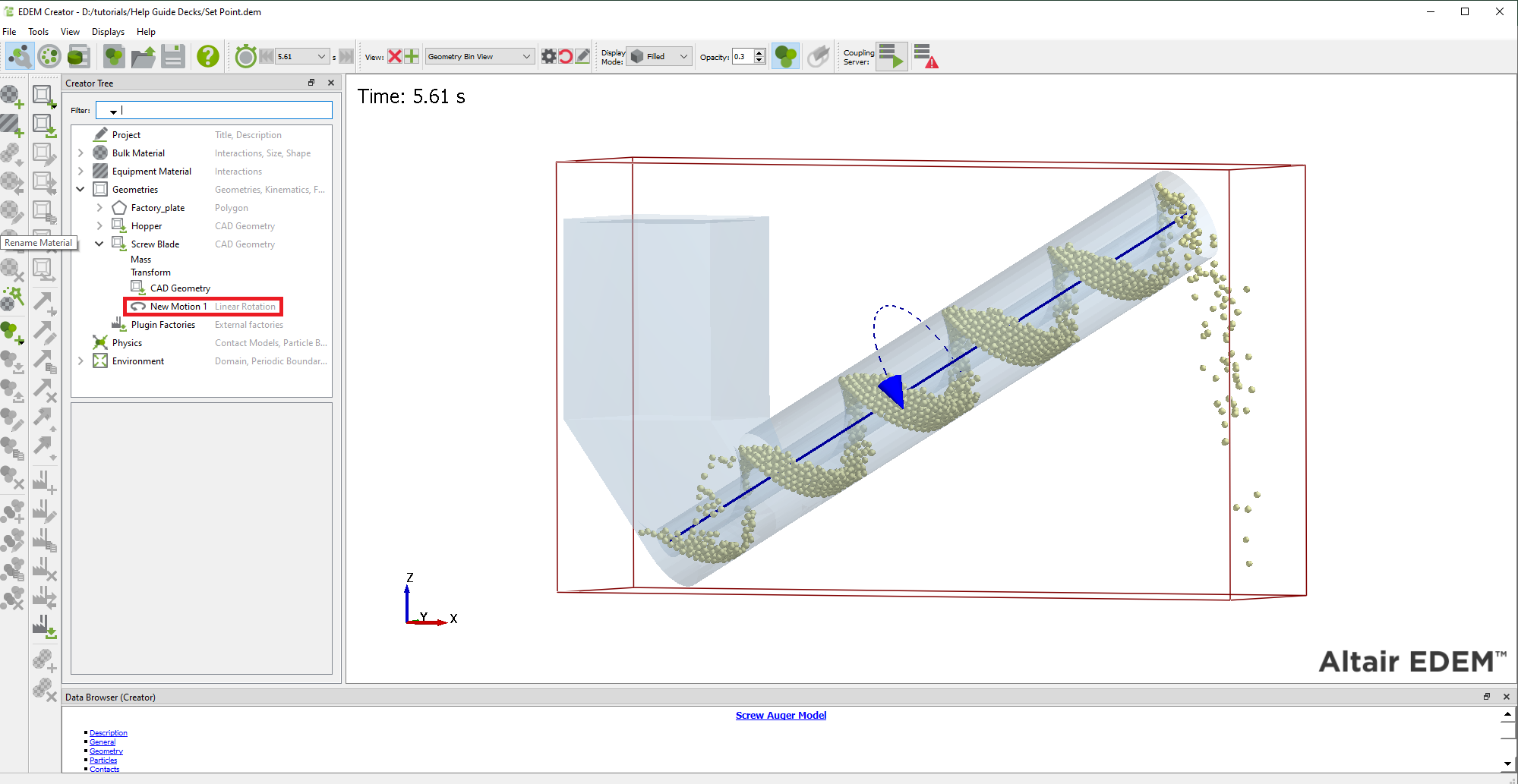
The recommended torque export is therefore the following:
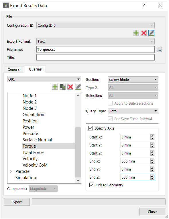
The torque is exported along the user defined axis which matches the axis of rotation of the auger.
Contacts Elements:
Affects all or any combination of specific particles types or geometry sections.
| Attribute | Components | Query Type |
| Contact Normal (Polyhedral) | X, Y, Z | Standard, Avg., Total, Min. or Max. |
|
Contact vector 1. |
Magnitude, X, Y, Z. |
Standard, Avg., Total, Min. or Max. |
|
Contact vector 2. |
Magnitude, X, Y, Z. |
Standard, Avg., Total, Min. or Max. |
|
Normal force. |
Magnitude, X, Y, Z. |
Standard, Avg., Total, Min. or Max. |
|
Normal overlap. |
N/A |
Standard, Avg., Total, Min. or Max. |
|
Number of contacts. |
N/A |
Avg., Total, Min. or Max. |
| Overlap Volume (Polyhedral) | N/A | Standard, Avg., Total, Min. or Max. |
| Penetration Depth (Polyhedral) | N/A | Standard, Avg., Total, Min. or Max. |
|
Position |
X, Y or Z. |
N/A |
|
Tangential force. |
Magnitude, X, Y, Z. |
Standard, Avg., Total, Min. or Max. |
|
Tangential overlap. |
N/A |
Standard, Avg., Total, Min. or Max. |
|
Custom property. |
Depends on number of elements. |
Standard, Avg., Total, Min. or Max. |
Bond Elements:
Affects all or any combination of specific particles types.
| Attribute | Components | Query Type |
|
End time. |
N/A |
N/A |
|
Normal force. |
Magnitude, X, Y, Z. |
Standard, Avg., Total, Min. or Max. |
|
Normal moment. |
Magnitude, X, Y, Z. |
Standard, Avg., Total, Min. or Max. |
|
No. of broken bonds. |
N/A |
N/A |
|
No. of intact bonds. |
N/A |
N/A |
|
Tangential force. |
Magnitude, X, Y, Z. |
Standard, Avg., Total, Min. or Max. |
|
Tangential moment. |
Magnitude, X, Y, Z. |
Standard, Avg., Total, Min. or Max. |
Geometry Elements:
Affects all or any individual section (as specified in the Creator).
| Attribute | Components | Query Type |
|
Center of mass. |
X, Y, Z. |
Standard, Avg., Total, Min. or Max. |
|
Compressive force. |
N/A |
Standard, Avg., Total, Min. or Max. |
|
ID |
N/A |
N/A |
|
Node n. |
X, Y, Z. |
N/A |
|
Orientation |
All, XX, XY, XZ, YX, YY, YZ, ZX, ZY, ZZ. |
N/A |
|
Position |
X, Y, Z. |
N/A |
|
Power |
N/A |
Total (-ive indicating power required to do work on particles) |
|
Pressure |
N/A |
Standard, Total Pressure, Max, Min. |
|
Surface normal. |
All, X, Y, Z. |
N/A |
|
Torque |
Magnitude, X, Y, Z. |
Standard, Avg., Total (Specify Axis), Min. or Max. |
|
Total force. |
Magnitude, X, Y, Z. |
Standard, Avg., Total, Min. or Max. |
|
Velocity |
Magnitude, X, Y, Z. |
Standard, Avg., CoG, Min. or Max. |
|
Angular velocity |
Magnitude, X, Y, Z. |
Standard, Avg., CoG, Min. or Max. |
|
Custom property. |
Depends on number of elements. |
Standard, Avg., Total, Min. or Max. |
Particle Elements:
Affects all or any individual particle type (as specified in the Creator).
| Attribute | Components | Query Type |
|
Angular velocity. |
Magnitude, X, Y, Z. |
Standard, Avg., Total, Min. or Max. |
|
Axial stress |
X, Y, Z |
Standard, Avg., Total, Min. or Max. |
|
Compressive force. |
N/A |
Standard, Avg., Total, Min. or Max. |
|
Coordination Number. |
N/A |
Standard, Avg., Total, Min. or Max. |
|
Diameter |
N/A |
Standard, Avg., Total, Min. or Max. |
|
ID |
N/A |
N/A |
|
Moment of inertia. |
Magnitude, X, Y, Z. |
Standard, Avg., Total, Min. or Max. |
|
Kinetic energy. |
N/A |
Standard, Avg., Total, Min. or Max. |
|
Mass |
N/A |
Standard, Avg., Total, Min. or Max. |
|
Number of particles. |
N/A |
Avg., Total, Total over time, Min. or Max. |
|
Orientation |
All, XX, XY, XZ, YX, YY, YZ, ZX, ZY, ZZ. |
N/A |
|
Position |
X, Y or Z. |
N/A |
|
Potential energy. |
N/A |
Standard, Avg., Total, Min. or Max. |
|
Residence Time |
N/A |
Standard, Avg., Min or Max. |
|
Rotational kinetic energy. |
N/A |
Standard, Avg., Total, Min. or Max. |
|
Stress tensor. |
XX, XY, XZ, YX, YY, YZ, ZX, ZY, ZZ |
Standard, Avg., Total, Min. or Max. |
|
Torque |
Magnitude, X, Y, Z. |
Standard, Avg., Total, Min. or Max. |
|
Total energy. |
N/A |
Standard, Avg., Total, Min. or Max. |
|
Total force. |
Magnitude, X, Y, Z. |
Standard, Avg., Total, Min. or Max. |
|
Velocity |
Magnitude, X, Y, Z. |
Standard, Avg., Total, Min. or Max. |
|
Volume |
N/A |
Standard, Avg., Total, Min. or Max. |
|
Von Mises |
N/A |
Standard, Avg., Total, Min. or Max. |
|
Custom property. |
Depends on number of elements. |
Standard, Avg., Total, Min. or Max. |
Details on Stress Calculation
Stress Tensor
The stress tensor for a single discrete element (particle) is calculated as follows:
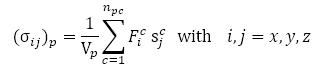
Where Vp is the volume of the particle p, npc the number of particles in contact with the particle p, Sc the vector connecting the particle center with the cth contact point and Fc the cth contact force.
Note: For averaging in a representative volume (bin), the stress tensor must be divided by the volume of the bin.
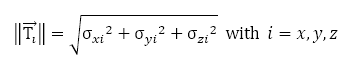
Axial Stresses
Axial stresses are calculated as follows:
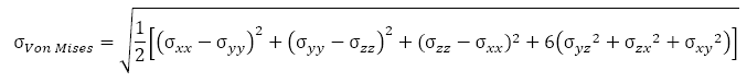
Von Mises Stresses
Von Mises stresses are calculated as follows:
Truncating Results
The Truncate option is used to remove results data (time steps) from your simulation. Data can be removed entirely, or simply 'thinned out' by removing every nth result.
Select File > Truncate File. The Truncate file dialog is displayed:
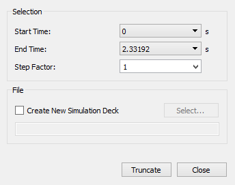
Set the Start and End Times. This defines the times steps between which you would like to remove data. Only full time steps can be truncated: you cannot truncate time steps from partial saves.
Set the Step Factor. A factor can be selected from the list or a new value entered directly. This determines how often a time step in the range is removed. If the step factor is set to one, every time step will be retained. If it is set to greater than one, the data in the range will effectively be 'thinned out'. The greater the step factor, the more data is removed.
By default the selected data will be truncated from the current simulation deck. Tick Create New EDEM Simulation Deck to truncate to a new simulation deck. The original deck is unaffected.