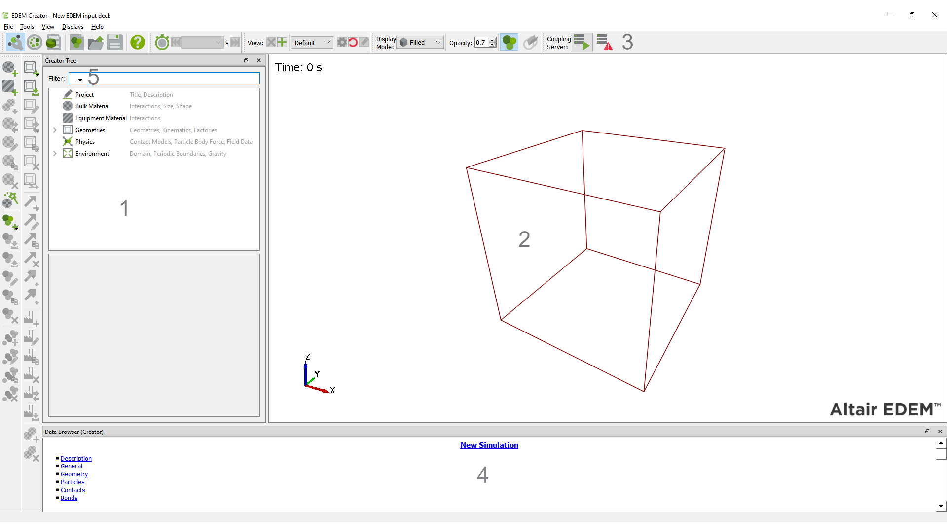
About the EDEM Creator
The Creator is used to setup and initialize your model. It is where you or import particles and geometries and define the other model parameters.
-
Creator Tree
-
Viewer
-
Creator Toolbar and Menu Bar
-
Data Browser (Creator)
Creator Tree
The Creator Tree is displayed on the left side of the EDEM window. It contains information about the Project, Bulk Material, Equipment Material, Geometries, Physics and Environment.
Viewer
The Viewer displays 3D representations of your particles, geometry, and fields (if applicable). The rotation, position and zoom factor of the Viewer are controlled using the mouse.
Creator Toolbar and Menu Bar
Toolbar
| Icon | Name | Description |
|
|
Creator |
Click to switch to the Creator. |
|
|
Simulator |
Click to switch to the Simulator. |
|
|
Analyst |
Click to switch to the Analyst. |
|
|
New |
Click to start a new model. |
|
|
Open |
Click to open an existing model. |
|
|
Save |
Click to save your model. |
|
|
Help |
Click to view the online help. |
|
|
Change Time Step Back |
Move to the first time step in the simulation. |
|
|
Change Time Step Forward |
Move to the last time step in the simulation. |
|
|
Start Coupling Server |
Click to start the Coupling Server. |
|
|
Coupling Server Disabled |
Shows the Server is not running. |
|
|
Server Awaiting Connection |
Shows the Server is started but not connected. |
|
|
Server Connected |
Shows the Server is connected. |
|
|
Stop Server |
Click to stop the Coupling Server. |
|
|
Filled Display Mode |
Click to display geometry filled. |
|
|
Mesh Display Mode |
Click to display geometry |
|
|
Points Display Mode |
Click to display geometry |
|
|
Display Particles |
Click to display or hide all particles. |
|
|
Display Cylindrical Periodic Boundary Conditions |
Click to visualize cylindrical periodic boundary. |
|
|
Add Bulk Material |
Click to add a Bulk Material to the simulation. |
|
|
Add Equipment Material |
Click to add an Equipment material. |
|
|
Save Material Block |
Click to save block of material for material bed. |
|
|
Transfer Material from Database Materials |
Click to transfer materials to and from the Material Database. simulation materials with material database. |
|
|
Rename Material |
Click to rename the selected material. |
|
|
Copy Material |
Click to copy the selected material. |
|
|
Delete Material |
Click to delete the selected material. |
|
|
Open GEMM Wizard |
Click to open the GEMM Wizard. |
|
|
Add Particle |
Click to add a particle to a Bulk Material. |
|
|
Import Particle |
Click to import a particle to a Bulk Material. |
|
|
Export Particle |
Click to export a particle. |
|
|
Rename Particle |
Click to rename a particle. |
|
|
Copy Particle |
Click to copy a particle. |
|
|
Delete Particle |
Click to delete a particle. |
|
|
Add Sphere |
Click to add a Sphere to a particle. |
|
|
Copy Sphere |
Click to copy a particle Sphere. |
|
|
Delete Sphere |
Click to delete a particle Sphere. |
|
|
Add a Geometry |
Click to access geometry add drop down list. |
|
|
Add a Box |
Click to add box from geometry drop down list. |
|
|
Add a Cylinder |
Click to add cylinder from geometry drop down list. |
|
|
Add a Polygon |
Click to add polygon from geometry drop down list. |
|
|
Import a Geometry |
Click to import a geometry from 3D CAD file. |
|
|
Rename a Geometry |
Click to rename a geometry sections |
|
|
Copy a Geometry |
Click to copy a geometry sections |
|
|
Delete a Geometry |
Click to delete a geometry section. |
|
|
Merge a Geometry |
Click to merge geometry sections |
|
|
Replace a Geometry Part |
Click to replace geometry with alternative one. |
|
|
Add a Motion |
Click to access Motion drop down list. |
|
|
Add Linear Translation |
Click to add linear translation to geometry. |
|
|
Add Linear Rotation |
Click to add linear rotation to geometry. |
|
|
Add Sinusoidal Translation |
Click to add sinusoidal translation to geometry. |
|
|
Add Sinusoidal Rotation |
Click to add sinusoidal rotation to geometry. |
|
|
Add Conveyor Translation |
Click to add conveyor translation to geometry. |
|
|
Add Conveyor Rotation |
Click to add conveyor rotation to geometry. |
|
|
Rename a Motion |
Click to rename a Motion. |
|
|
Copy a Motion |
Click to copy a Motion, this can be applied to the current geometry or an alternative one. |
|
|
Delete a Motion |
Click to delete a Motion. |
|
|
Move Motion Up |
Click to reorder Motion. |
|
|
Move Motion Down |
Click to reorder Motion. |
|
|
Add Force |
Click to add force to geometry |
|
|
Add Torque |
Click to add torque to geometry |
|
|
Add Factory |
Click to add a material factory to the simulation. |
|
|
Import Factory |
Click to import a factory. |
|
|
Rename Factory |
Click to rename factory. |
|
|
Copy Factory |
Click to copy factory. |
|
|
Delete Factory |
Click to delete factory. |
|
|
Change Factory |
Click to change from static to dynamic factory. |
|
|
Add Material Block |
Click to add a material block to a geometry |
|
|
Delete Material Block |
Click to delete a defined Material Block |
|
|
Show Scale Grid |
When displaying particle shapes show/hide grid. |
|
|
Show Origin |
When displaying particle shapes, show origin and particles as a mesh. |
|
|
Highlight Surface/Meta-Particle |
Highlights selected surface of particle shape or selected Meta-Particle |
|
|
Add Meta-Particle |
Click to add a Meta-Particle. |
|
|
Rename Meta-Particle |
Click to rename a Meta-Particle. |
|
|
Copy Meta-Particle |
Click to copy a Meta-Particle. |
|
|
Delete Meta-Particle |
Click to delete a Meta-Particle. |


Note that in addition to the icon system there are a series of keyboard shortcuts shown alongside the Creator Tree for the same actions as the icons. The Delete key also can be applied to single and multiple selections.
File Menu
- Open: Open an existing model.
- New: Start a new model.
- Save: Save the current model.
- Save As: Save the current model with a specific name or to a specific location.
- Geometry Transforms: Export geometry transforms.
- Import Config. Import a config (*.dfg) file.
- Export Config. Export a config (*.dfg) file.
- Creator: Select to switch to the Creator.
- Simulator: Select to switch to the Simulator.
- Analyst: Select to switch to the Analyst.
- Recent Files: A list of recently opened files. Select a file to open it.
- Quit: Quit EDEM.
Tools Menu
- Options: Access the global options dialog containing settings for the following items:
- Additional Components
- RecurDyn Coupling
When this checkbox is enabled, a new option called “Import Geometry from RecurDyn” will appear when you right click on Geometries in the Creator Tree. This allows you to read a *.wall file, produced by RecurDyn, allowing you to import a geometry from RecurDyn.
Once the geometry is imported and the coupling interface is enabled, RecurDyn can control the geometry motion in EDEM. The forces experienced by these geometries are passed back to RecurDyn and any motions arising due to these forces are calculated in RecurDyn. - Abaqus Coupling
When this checkbox is enabled, a new option called “Abaqus Co-Simulation” will appear in the Analyst under the Tools Menu allowing you to couple EDEM with Abaqus FEA.
- RecurDyn Coupling
- Data Browser
The data browser options are used to configure the color of the data browser text and background. - Display Options
- Background Color: This option is used to change the fill color of the Viewer background. The background can be colored with a solid or gradient fill. The color change will affect the Creator, Simulator and Analyst.
- User Logo: This option can be used to apply a custom logo to the Viewer window. The logo can be positioned, scaled, faded as required.
- File Locations
The file location options are used to determine the location of the following:- Materials Database: The location of the users materials database, used to store and transfer materials to and from simulations.
- GEMM Database: The location of the Generic EDEM Material Model database, used to set the location of the database to import to EDEM.
- Contact Models: The location of custom (user-defined) contact models, see the EDEM Programming Guide for more information on user defined models.
- Particle Body Force: The location of custom (user-defined) particle body force models.
- Particles: The location of particles saved independently of the model for reuse in other projects.
- Factories: The location of any user-defined factories.
- Mouse Configuration
Used to configure how the mouse is used to alter the display in the Viewer.- Camera Actions: Change the mouse button and modifier key used to pan, track, zoom and rotate the camera. Modifier keys assign keyboard buttons to press to perform the specified camera action. Choose any unique combination of three mouse buttons and three keys for each motion.
- Rotate on Axis: Change the mouse button and modifier key used to rotate on an axis. You can also set whether to rotate on the model axis or the screen axis for both the horizontal and vertical rotations.
- Bin Control: Bin tools and Sensor tools in the Analyst can be moved through mouse selection. First select the bin and the color changes from blue to green. Then using the Bin Control Modifier (default CTRL) the bin can be moved through the Pan, Track, Axis Locked Rotation and Free Rotation options. The Bin Control Modifier can be set by the user to any of the options available in the drop-down box.
- Mouse Sensitivity: The mouse sensitivity can be altered independently for tracking and zooming. You can also specify modifier keys for each sensitivity setting.
- Rendering Options
- Use legacy particle display: This option is checked if EDEM cannot use the computer Graphics Card. Typically applied when using Remote Desktop or when using EDEM on computer with out-of-date graphics card drivers.
- Display Templates: 3D CAD files can be used as particle templates. Templates can be used as a guide (outline) to help define the shape of your particle in the Creator as well as providing, if desired, the shape for calculation of the center of gravity and mass moments of inertia, or as a display option in the Analyst.
When a model containing a particle template is saved, an extra file (.ptf) is created. If this file is deleted, the template information will no longer be stored within the model
- Section Options
- Creator
- Timestep on Switch: When switching to the Creator, it will it automatically load the last time step.
- Hide Electrostatics: This should be ticked unless using the electrostatics contact model, this option enables a series of options to appear in the interface which are specific to the electrostatic contact model.
- Simulator
- Compress Save Data: When checked EDEM will compress simulation data as it is saved to minimize file size. Turning this off will reduce the time taken to save but increase file size.
- Timestep on Switch: When checked the last time step will be displayed when switching to the simulator, otherwise the current time step will be displayed.
- Analyst
- Timestep on File Load: Models can be loaded into the Analyst with the first or last time step appearing first.
- Display:
- Auto Update Display: Toggles whether the display is automatically updated when changing display properties, or whether an Apply button is present and must be pressed first.
- Axis Key: Turn the display of the axis key in the Viewer on or off.
- Domain Box: Turn the display of the boundary box (marking the domain edges) in the Viewer on or off.
- Timestamp: Turn the display of the time stamp in the Viewer on or off.
- Data Export Defaults
- Notation: Specifies the default format when exporting data via the data export tool. Options are: Smart, Fixed-Point and Scientific.
- Precision: Specifies the corresponding default precision when exporting data via the data export tool.
- Creator
- Simulator Engine
Choose from the standard or GPU simulator engine. On creating a new simulation the Simulator Engine will default to the one set in the Tools Menu. When in the Simulator the user can change the engine used and this information is stored per simulation in the simulation_name.dfg file. When opening existing simulations the displayed engine will be the last saved setting for the simulation.
When starting a new simulation EDEM defaults to the Maximum Cores available on the local PC. Users can set the default number of Cores via the Simulator Engine > Default Number of Cores menu. This can be set once per user and then EDEM will default to the chosen setting.

- Units
- The units configuration dialog is used to set the measurement units used throughout EDEM.
- Additional Components
View Menu
-
Show Particles: Turns the particle display in the Creator on or off.
-
Themes: Show the EDEM interface with Legacy Theme (default) or Dark Theme.
Displays Menu
Split the EDEM view window into multiple displays, this allows multiple viewer windows to review different view-points of the model in each window.
Help Menu
- Help: The help menu brings up the relevant information regarding the EDEM interface.
- About EDEM: The about box provides information about the current version of EDEM. The EDEM Version and Revision number are useful information to provide EDEM technical support when discussing support cases.
- About Altair Simulations Products: The About Altair Simulation Products gives acces to the Copyright notices, Altair website, License Agreements and Customer Support.
Data Browser (Creator)
The Data Browser is an .html page that displays detailed information about your model. The information displayed differs between the Creator, Simulator and Analyst. Right click in the Data Browser and choose Save to save the information in an .html file. There are five sections in the Data Browser within the Creator:
Description
The description as defined in the Project section of the Creator Tree.
General
-
Gravity: Details of the gravity acting in your model as specified in the Creator Tree.
-
Materials: A list of all materials used in the model and their properties, as specified in the Materials Editor.
-
Energy: The total energy in the model at the current time. It is the sum of the kinetic energy, potential energy and the energy in any contacts taking place.
Geometry
-
Domain: The dimensions of the domain as specified in the Creator Tree.
-
Sections: Each section is the model and its properties are listed.
-
Geometry Totals: Totals. Details of the number of elements that make up each section of geometry.
Particles
-
Particles: A list of each particle type used in the model and their properties. This contains either sphere data for Multi-Sphere, Sphero-Cylinder data or mesh data for polyhedral particles.
-
Factories: Details of each factory used in the model and their properties. Properties are as specified in the Creator Tree. The total number of particles created by each factory is also listed.
-
Particle Totals: The total number of particles in the model at the current time. Totals for each particle type are also listed.
Contacts
-
Interactions: A list of the interaction types taking place in the model as specified in the Materials Editor.
-
Contacts: Lists the total number of contacts in progress at the current time. The contacts are broken down into contact types: For example number of particle A - particle B contacts or number of particle B - surface A contacts. The total number of collisions that have taken place during the time step are also listed.
Bonds
-
Bond Totals: Lists the total number of bonds, total number of intact and broken bonds and number of bonds intact/broken between particle pairs.