Creator Tree-Bulk Material
Every particle or section of geometry used in a model is made of a particular material. All materials and the interactions between them must be defined in the Bulk Material or Equipment Material tree. Materials can be created directly in the simulation or imported from the Materials Database. All materials defined in the Materials section are stored within the model.
Add Bulk Material
A Bulk Material contains the particle bulk material properties, the particle shape and size distribution. To add a Bulk Material to a model:
-
Right click and choose add Bulk Material or use
 to add the material, rename the material as appropriate.
 -
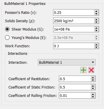
Enter the Poisson's Ratio, Shear Modulus (or Young's Modulus), Solids Density and Work Function (if applicable) into the relevant fields.
You can also choose to Copy to create a duplicate of the currently selected material. To remove a material from a model, select the material then click the  button.
Interactions
Interactions are used to define how materials act when they come into contact with each other. Interactions must be defined for all materials used in your model, including the interaction that occurs when a material comes into contact with itself: for example when two particles of the same material collide.
To define an interaction between two materials:
-
Select the first material from the list of Bulk Materials in the Creator Tree.
-
Click the + button in the Interactions section.
-
Select the second material from the Select Material dialog.
-
Enter values for the Coefficient of Restitution, Coefficient of Static Friction and Coefficient of Rolling Friction into the relevant field.
Interactions have to be set for every combination of Bulk Materials and their interactions with other Bulk Materials and Equipment Materials.
Add a MultiSphere Particle Shape
A multi-sphere particle is defined using one or more spherical spheres. Multiple surfaces spheres can be overlapped to create multi-sphere particles.
Right click on the Bulk Material and choose Add MultiSphere Particle or use the  icon. This creates a new particle shape in the Creator Window:
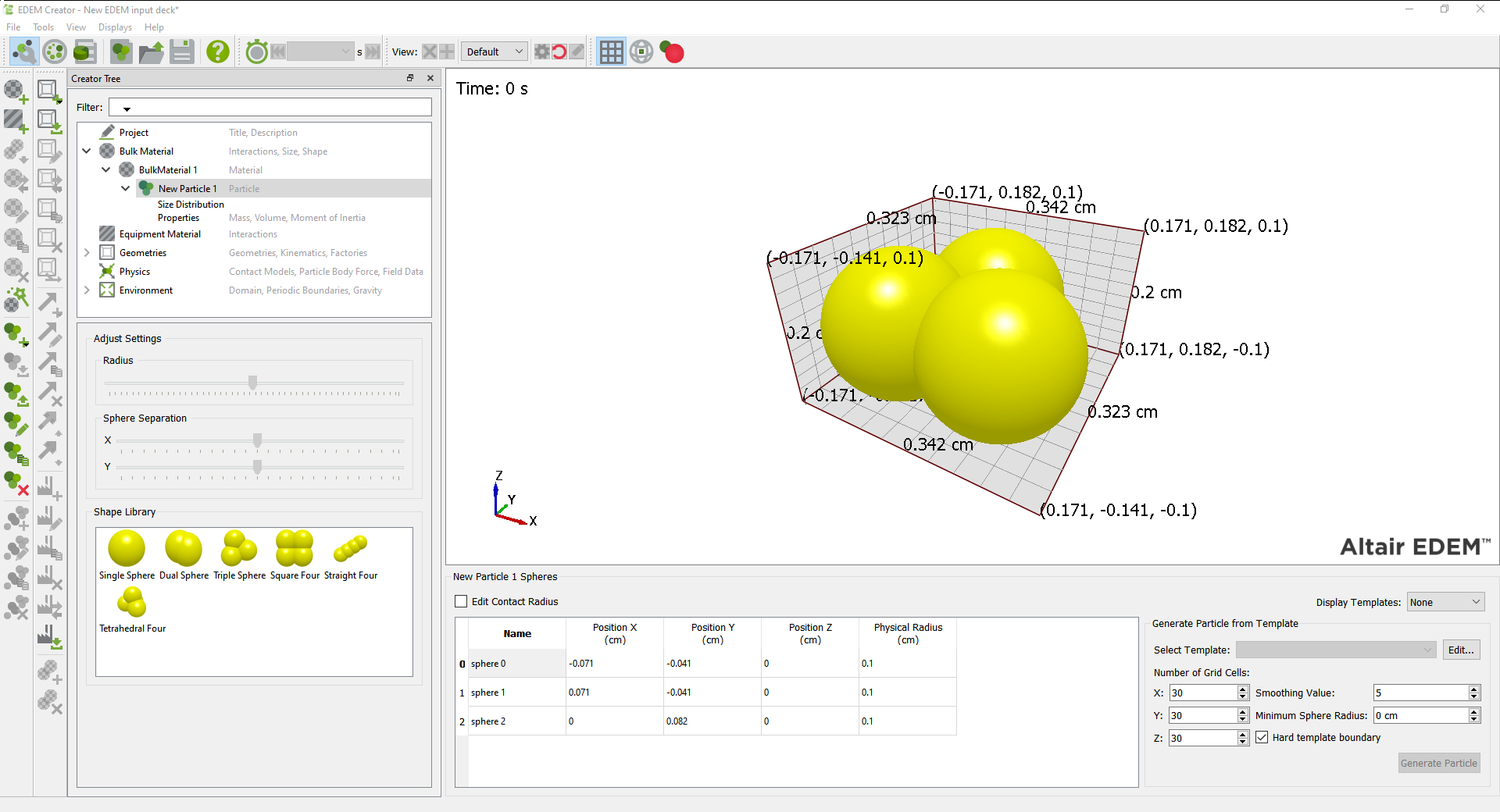
A multi-shpere particle can be made from multiple spheres. In the image above each sphere is called sphere N where N is between 0 and the ‘number of spheres -1’.
The user can modify the X,Y,Z position of each sphere for the particle shape, user can also add, copy or remove a sphere from the particle using the icons  ,
,  ,
,  or the right click menu. Duplicating a sphere adds a new sphere in the list, the radius and position can then be modified by the user.
The sphere table can be copied and pasted from an external source. The table must match the format of the table in EDEM.
Select Contact Radius when the particle has a different interaction (contact) which is not on its physical surface, such as contact radius due to other (long-range) forces acting upon it or inter-particle bonds. This option should only be used with a relevant user-defined contact model. When two contact radii overlap the contact force calculation is entered into; the physical radius of the spheres is used to calculate the magnitude of the physical contact force however user-defined forces can be applied when the contact radii overlap.
For multiple spheres, use the Position X, Y and Z options to define their relative positions. Note that multi-sphere particles should be centered on the origin along the principle axes to ensure that the moments of inertia are calculated correctly.
Add a Particle Shape from Library
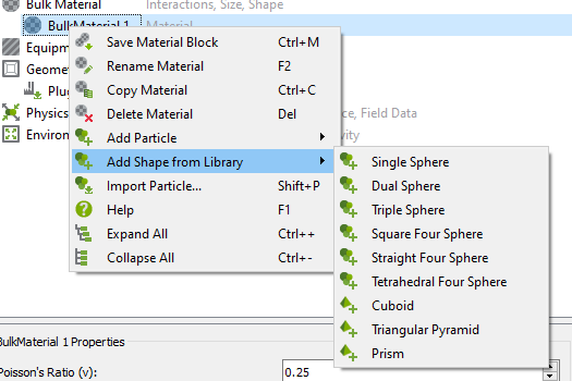
A particle can be added and described manually or can be chosen from a list of shapes using the Add Shape From Library option.
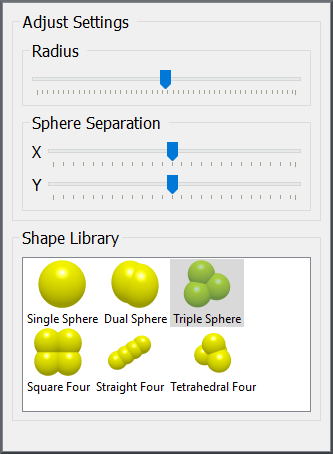
On choosing this option the radius, X, Y, Z position and sphere separation (in the X and Y axes) of each shape can be set.
Modify Particle Shape
A particle shape can be modified by changing the values in the table. In addition, selecting the Particle and choosing Modify Shape will show the following toolbar:
The Radius slide bar changes the radius (scale) of the shape while maintaining the same shape profile. Surface Separation will change the surface separation (shape profile) by modifying the sphere positions in the X axis or Y axis.
Add a Sphero-Cylinder Particle Shape
A Sphero-Cylinder particle is defined by a length and a radius. The length is given by the total length of the particle including the rounded ends.Switching between Multi-Sphere, Sphero-Cylinder and Polyhedral particles is only supported at time step 0s.

Right click on the Bulk Material and choose Add Spherocylinder Particle or use the ![]() icon. This creates a new particle shape in the Creator Window:
icon. This creates a new particle shape in the Creator Window:

Add a Polyhedral Particle Shape
A Polyhedral particle is defined either by using one of the default polyhedral particle shapes or by an imported CAD geometry. Selecting “Add Polyhedral” creates a new Polyhedral particle in the creator Window. The Polyhedral solver supports convex polygons either defined using the EDEM polyhedral shape library or an imported CAD geometry. Switching between Multi-Sphere, Sphero-Cylinder and Polyhedral particles is only supported at time step 0s.
Adding Default Polyhedral Particle Shapes
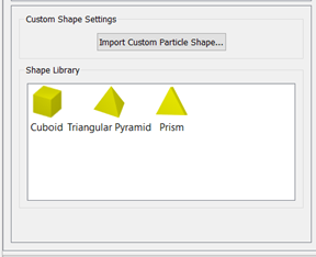
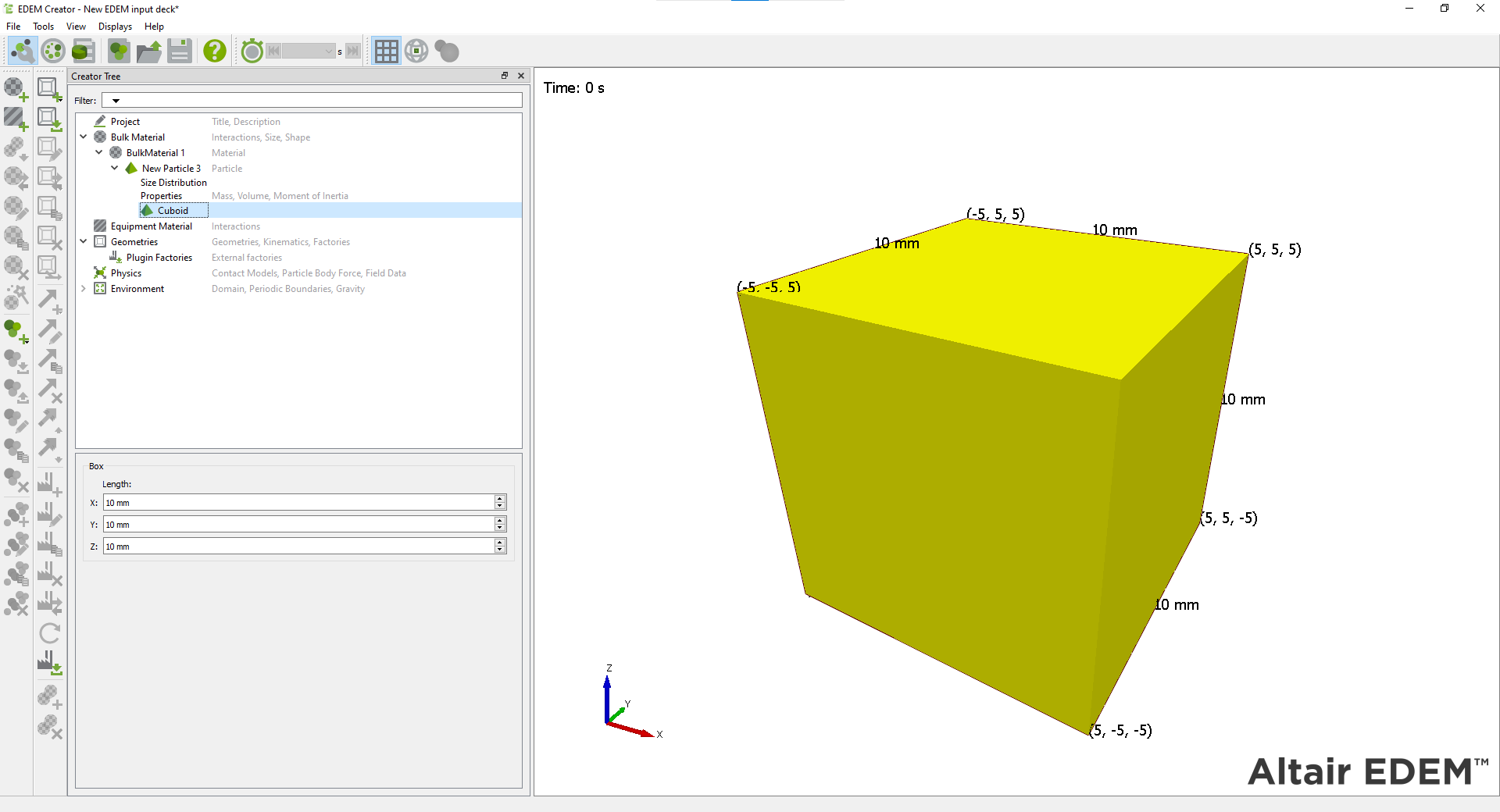
Within the Particle menu, there is an option to define the shape of the particle called Cuboid, Triangular Pyramid, Prism or CAD Geometry.
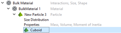
To change a particle shape once a particle has been defined, select the particle name and in the shape (grey box) select “Modify Shape”, the three default particle shapes are now available to select.
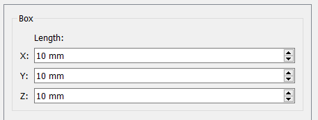
Cube
Selecting this for Cuboid gives the option to edit the X,Y and Z components of the cuboid.
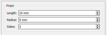
Prism
The Prisms Length, Radius and number of sides can be defined
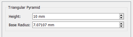
Triangular Pyramid
The Height and Base radius of the Triangular pyramid can be defined
Import Custom Particle Shape
Select Import Custom Particle Shape.. to select a CAD geometry to import as a particle shape. These can only be convex geometries. The geometries will be centered based on their center of mass when Calculate Properties is selected. Editing of the particle size can be done by changing the size distribution under “Size Distribution"
Delaunay Meshing
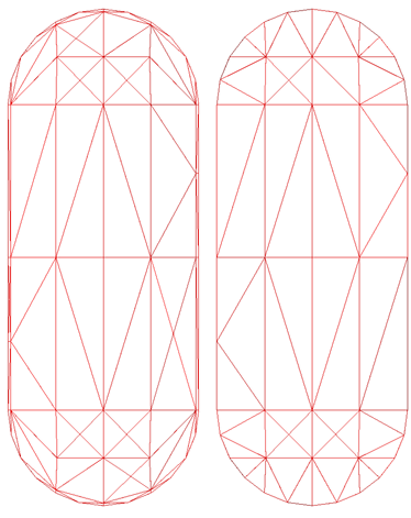
When importing a custom particle shape there is now a Delaunay meshing process that is carried out to ensure the particle is convex. This is based on Delaunay meshing and will generate a shape compatible with the EDEM Polyhedral solver. This option should be used on shapes which are near convex, but through the meshing process or CAD generation have small amounts of concavity. Delaunay triangulation is carried out to maximize the minimum angle of each triangle. This results in a mesh that doesn’t contain high aspect ratio or slither triangles and often reduces the number of triangle elements.
Below is an example of the results of this change:
Standard Import Delaunay Import
The Delaunay mesh is created so that no mesh node is inside the circumsphere of any triangle element. The following describes this in 2D with circles but the same principles are applied with spheres for 3D meshes.
Below is an example where a triangle element cannot be formed because the node is within the circumcircle of another triangle and therefore does not satisfy the Delaunay criteria.

Delaunay mesh that satisfies the Delaunay criteria:

Using a Particle Template (Multi-Sphere)
Mesh files created in other packages can be used as particle templates. A template can be used as a guide to create your particle and its properties automatically calculated from it. We recommend using a template if your model uses multi-sphere particles.
To use a template:
- Go to the Tools > Options > Options menu.
- Click the Import button and navigate to the file of your choice. Any templates used in your model must first be imported here.
- Select view > Templates to display the imported template or when a particle shape is selected choose from the Templates option.
- Create spheres to match the template outline.
Data relating to the particle template is stored in the *.ptf file. If this file is deleted, the template information will no longer be stored within the model.
Generate Particle from Template (Multi-Sphere)
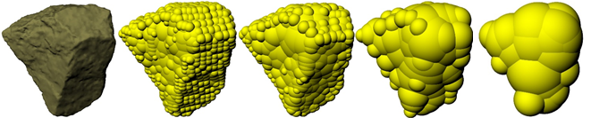
The Generate Particle from Template option is used to create complex particle shapes based on a CAD template. This feature uses an imported mesh template of the particle and adds spheres to fill that volume generating a multi-sphere particle to fill the volume.
To use the sphere fitting tool, first import a template. This can be done from the options menu (see Using a Particle Template) or by clicking the Edit button, which will launch the Options menu.
Click the Import button and navigate to the file of your choice. Any templates used in your model must first be imported here.
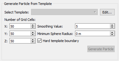
Number of Grid Cells
Enter the number of grid cells, in the X, Y and Z direction. This will generate a grid around the imported template. Increasing the number of grid cells will improve the fidelity of the generated multi-sphere particle but will also increase the computation cost. Click hereClick here for an overview of how the sphere fitting tool works.

Figure: 2D Example showing star template and generated grid
Using the generated grid, all cells within the volume are identified and the cells containing the boundary of the object are identified.

Figure: Cells identified as internal (red), boundary (blue) and external (Green)
For each of the inner cells, the distance to the boundary cells is calculated and the shortest path is identified.

Figure: Showing all the paths from the internal cell to boundary cells and the shortest path highlighted in red
Using this shortest path a sphere is generated between that cell and the nearest boundary cell.

Figure: Sphere generated with a radius equivalent to the shortest path
This is repeated for all inner cells and spheres are generated from the inner cell to the nearest boundary cell.

Figure: All the spheres generated for this star shape using these grid settings and the shortest paths used for the sphere
Smoothing Value
After all spheres are generated, an optimization stage is performed, to remove any unnecessary spheres. When a smoothing value is greater than 1 the fidelity of the particle will be reduced and the total number of spheres will decrease.
|
Smoothing Factor |
1 |
2 |
5 |
10 |
|
Number of Spheres |
835 |
363 |
69 |
22 |
|
Smallest Sphere (mm) |
56 |
75 |
131 |
224 |
Minimum Particle Size
The minimum particle size is used to ensure that there are no particles in the multi-sphere which are excessively small. Smaller spheres will require simulations to be run at a smaller time step, and therefore will be more computationally expensive. It is recommended that this setting is only adjusted after a few generation attempts as other options such as the hard boundary option may drastically affect the radius of the spheres. At this point it is also possible to use the sphere table from the previous generation to visualize the radii of spheres in the particle and manually find a suitable value to use as a minimum radius.
Hard Particle Template
The smoothing value will grow particles outside the template boundary. The hard template boundary will scale particles towards the center of the template. As stated above, the smoothing value increases the size of the spheres used to populate the particle. This can lead to a particle that is much larger than the template it was created from. Checking the hard template boundary option will scale the particle back down towards the center of the template to ensure that the created particle is of similar size to the template this option should be checked when using a large smoothing value.
NB this should not be used in instances where the shape’s center of the bounding box is outside the template such as toroids as the particles will scale towards that point.
Setting the Size Distribution
The size distribution is set for the particle shapes in each Bulk Material including meta-particles. The scaling options for the size distributions are all relative to the defined particle size. If the ‘scale by Radius’ option is used, all length dimensions will be scaled in direct proportion to the value specified. If 'Scale by Volume’ is specified all length dimensions will be scaled to the cube-root of the value specified.
The size distribution options are:
- Fixed. All particles are created with an equal size and volume.
- Random. Particle radii are randomly sized within a set size range: for example, with a minimum size of 0.5 and a maximum of 1.5 and scale by Radius selected, particles no smaller than half and no bigger than one-and-a-half times the size of the standard size are produced.
- Normal distribution. Particle shapes have a normal distribution. The average (mean) particle radius or volume and the standard deviation must be defined. The mean and standard deviation should both be normalized i.e. the mean is the ratio of the mean to the input particle radius or volume and similarly for the standard deviation. Use the capping options to cap the maximum and minimum particle sizes.
- Log-normal distribution. Particle shapes have a log-normal distribution. The average (mean) particle radius or volume and the standard deviation must be defined. The mean and standard deviation can be defined using a logarithmic or linear scale. With a logarithmic scale, the input values are exponential functions. For example, a mean value of 1 in the logarithmic scale denotes an actual scaling of 2.718 in the linear scale. Note that the mean and standard deviation should both be normalized i.e. the mean is the ratio of the mean to the input particle radius or volume and similarly for the standard deviation.
- User Defined. For mass generation of particles only, input a scale and percentage of total mass to be generated at that scale. Data can also be imported from CSV files where the first column is the scale and second column is percentage of mass. This data can also be pasted directly into the table. Percentage mass values must add up to 100%. User Defined size distributions can only be used with Mass Generation factories, number of particles (total number or number per second) factories are not supported.
Calculate Particle Properties
MultiSphere
The particle mass, volume and inertia need to be set. These can be calculated automatically by EDEM or input manually.
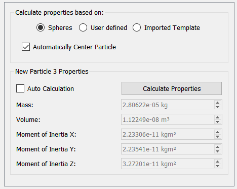
Automatically Calculate Properties:
- Select whether to calculate using the spheres that make up your particle, or (preferably) from an imported template.
- Check whether you want to automatically center the particle when calculating the moments of inertia. Unchecking this option may result in non-physical results.
- Click Calculate Properties to calculate the mass, volume, and moments of inertia for the current particle.
- If Auto Calculation is selected then any changes to the defined Particle size or shape will automatically trigger the Calculate Properties tool.
Since random sampling is used to calculate particle properties, re-calculating for particles with multiple surfaces may result in slightly different values.
User Defined Properties:
Type values for each property into the relevant field. If a value turns red it is not recommended.
| Properties | Description |
|
Mass |
Mass of the particle. |
|
Volume |
Volume of the particle measured. |
|
Moment of Inertia X/Y/Z |
The moment of inertia is a measure of a body's resistance to angular acceleration. A particle consists of a number of spheres, i, each with mass mi and radius ri. If each sphere is a distance di from a particular axis of rotation, then the moment of inertia of the particle about that axis is given by:
You can input different values for the moment of inertia to take into account particles of varying material properties (such as hollow spheres). |

Sphero-Cylinder
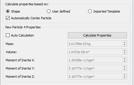
The mass of the particle will be calculated using the volume of the particle geometry if “Shape” or "Imported Template" is selected in particle properties. The Mass, Volume and moments of inertia can also be defined manually using the “User defined” option.
Polyhedral
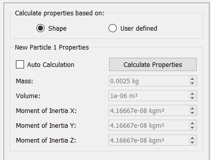
The mass of the particle will be calculated using the volume of the particle geometry if “Shape” is selected in particle properties. The Mass, Volume and moments of inertia can also be defined manually using the “User defined” option.
Copy Particle
Select the particle and choose Copy Particle  , this makes a copy of the particle, and associated spheres, with the name New Particle N.
Export Particle Shape
Once a particle has been defined it can be exported for use in other EDEM simulations. Right click on the particle and choose Export Particle  and save the file to your Particles folder (as specified using Tools > Options > File Locations). Files are exported in the .dem format.
Import a Particle Shape
Any particle created in EDEM can be exported for use in other models. To import a particle click the Import button  and navigate to your chosen file, only particles exported from EDEM simulations can be imported.
Transfer Material
The Transfer Material function  allows material, interaction data, meta-particles and Material Block data to be stored in a database file and transferred between simulations. Bulk Materials also contain the Particle Shape and Size Distribution information.
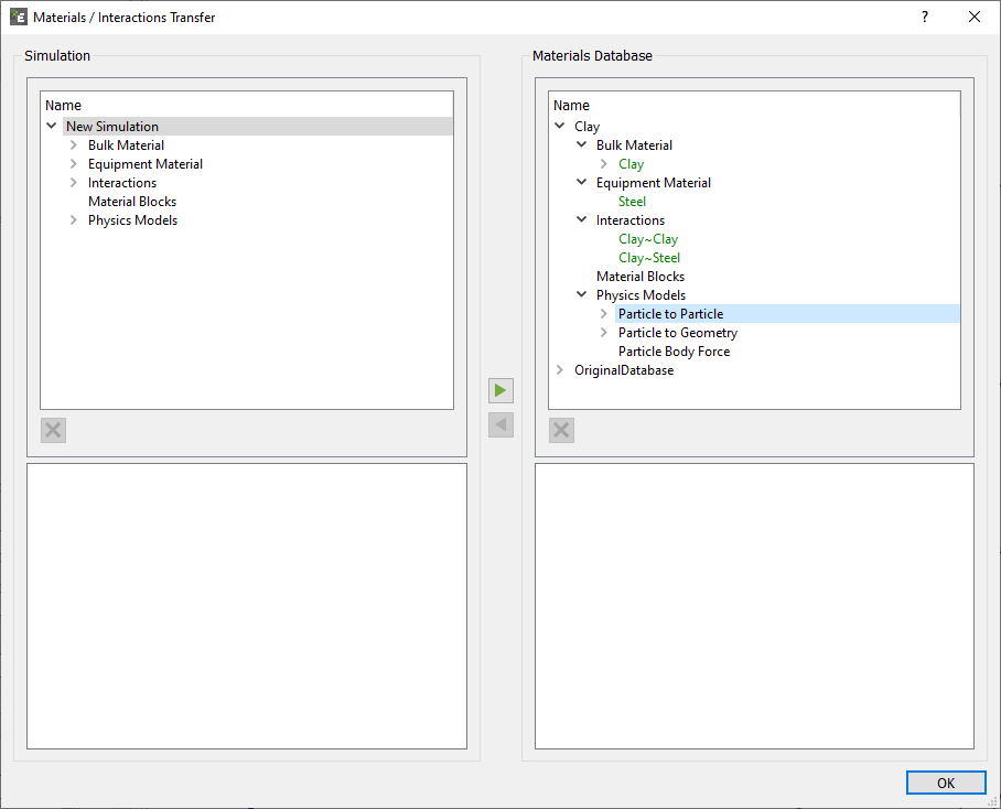
The Materials Database supplied with EDEM contains no example material types.
By default, the Materials Database (MaterialsDB.h5) is installed to the My Documents > Altair > EDEM folder. If you move the Materials Database (for example to a shared network folder for use by multiple clients), remember to update the location information in EDEM. To do this, select Tools > Options > File Locations then browse to the new location.
Transferring Materials to and from the Materials Database:
Any material or interaction defined in a model can be transferred to the materials database for use in other simulations. Similarly, materials and interactions can be imported from the database into your model.
To transfer a material to or from the database:
- Under the Bulk Material tab right click and choose Transfer Material. The Transfer dialog box appears.
- Click on the material to transfer. The material's properties are displayed at the bottom of the dialog.
- Click the appropriate arrow to transfer the material to or from the database.
If a material in the model and one in the database have the same name but different properties they are highlighted in red to indicate the conflict. If you continue with the transfer, one material will overwrite the other. If two materials have the same name and the same properties they are both highlighted in green.
If a meta-particle is in the simulation which matches the meta-particle name but is a different particle definition in the database it will be highlighted in red. If there is a miss-match with particle properties of the particles used to construct the meta-particle they will be highlighted yellow.
Equipment Materials will automatically be assigned to the Equipment Material section and Bulk Materials will automatically be assigned to the Bulk Material section of the Creator Tree. However the interaction information has to be transferred separately.
Adding Materials and Material Interactions to the Database:
Materials and material interactions can be added to the database by transferring from an existing simulation.
Note that materials defined in your database are not automatically added to any model. All materials used in a model must be defined directly in that model or explicitly transferred from the materials database.
By clicking this option, the particles inside the current simulation domain are stored in the form of a Material Block in the Material Database. The current simulation domain is defined as the bounding box as specified in the Creator Tree > Environment > Domain at the time step that the save material block option is selected. Saving a Material Block automatically saves the Bulk and Equipment Materials used for it together with the corresponding interactions. All this data will be available in any other EDEM deck through the Material Database.
The Contact Model specific information is also saved, for example if the Bonding V2 model is used the bond contact information is stored in the material block.
The purpose of this tool is to generate a bed of material just by assembling multiple copies of a Material Block. An alternative use of the Material Block is to take the output of one simulation and use it as an input to another, using the Dynamic Block Creation functionality.
In either case an initial simulation to obtain the Sample Block is necessary prior to moving back to the Creator to save the Material Block into the Internal Materials Database.
See “Add Material Block” in the Factories section of the Creator documentation.
Meta-Particles
A meta-particle is a collection of individual Multi-Sphere or Sphero-Cylinder particles bonded together using EDEM’s Bonding V2 contact model. The meta-particle feature allows the user to create flexible fiber/materials.
Creating a Meta-Particle
Right click on Bulk Material and select Add Meta-Particle, this will create a new Meta-Particle. Alternatively press Ctrl+Alt+P or  in the toolbar.
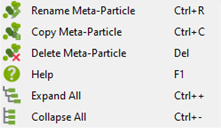
Right clicking on the newly created meta-particle will give the following options:
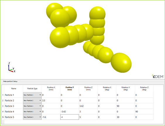
- To define a Meta-Particle, in the Creator Tree > Bulk Material > select the newly created meta-particle. The following empty dialog box should appear. Right click and select Add Particle. Repeat this to add the required number of particles for the desired Meta-Particle.
Under Particle Type, in the drop-down menus select the particles that are to make up the desired Meta-Particle.- To add, remove or copy a particle from the setup the following icons can be used respectively, ,
 ,
,  .
. - Any combination of different particles can be used to form meta-particles (this is not restricted to the same Bulk Material).
- Any arrangement that allows bonding upon creation can be used.
- To add, remove or copy a particle from the setup the following icons can be used respectively,
- Arrange the particles using the X, Y, and Z positioning and rotation coordinates so that the particles are next to each other with minimal overlap or separation
- If the particles are significantly overlapping, they will repel when the meta-particle is created and break apart.
- If the particles are spaced too far apart, they will not bond with each other upon creation and the meta-particle will not form correctly.
The  button highlights the particle, which is currently being edited, whichever particle is active in the table will be highlighted red.
NB. When using the Meta-particles in conjunction with the bonded model it is necessary to define the contact radius. When two contact radii overlap (as they will when setting up a meta-particle) this allows a bond to be formed between the particles.
The contact radius is advised to be 110% to 120% the size of the particle radius.
The larger to the contact radius, the more contacts that will be detected by the model, this will cause the simulation time to slow. A large contact radius of ~ 120% of the physical radius is only recommended for very flexible material to make sure breakage does not occur during bending.
Note. Multi-GPU factories will not generate Meta-Particles which cross the boundary between two GPUs. This will affect the random nature of particle generation.