Creator Tree-Environment
The model domain is the area where simulation takes place. It is defined in the Environment section of the Creator tree and indicated by the red box in the Viewer:
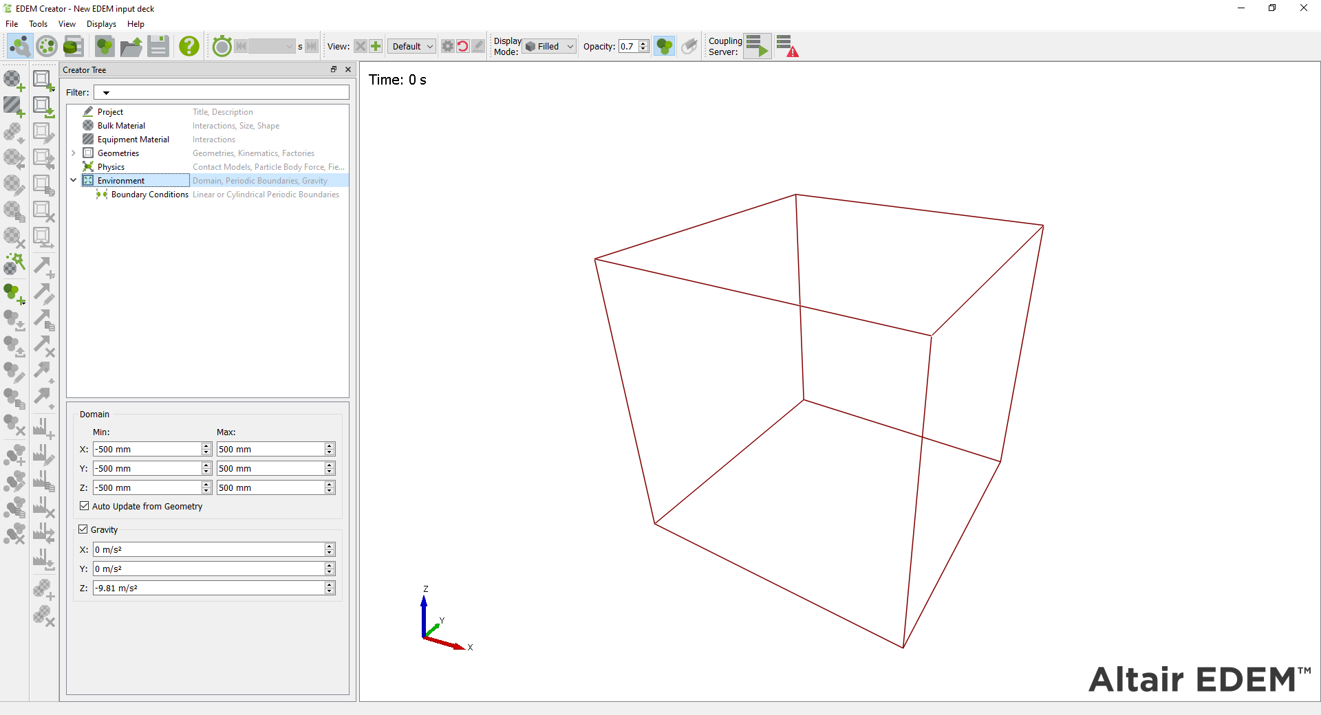
Particles that move out of the domain during the course of the simulation are permanently removed by the Simulator (unless a periodic boundary option has been selected). Geometry can move in and out of the domain during a simulation.
Defining the Model Domain
Domain size has an effect on simulation time - the larger the domain, the longer the simulation will take to run. Use the auto-update option to automatically fit the domain around any sections of geometry defined, thus creating the smallest domain possible.
Note: Geometries should not be placed totally coincident with the edge of the domain. Particles are removed as soon as they reach the domain edge, so cannot interact with any geometry placed there.
Gravity
Enable the gravity checkbox to set gravity in a given direction (X, Y, Z). The default settings are X: 0, Y: 0 and Z: -9.81 m/s2.
Environment Periodic Boundary Conditions
Periodic Boundaries (Linear)
Linear Periodic Boundaries enable you to set what happens to a particle once it leaves the domain. If the option is turned on for a particular direction, any particle leaving the domain in that direction will instantly re-enter it on the opposite side.
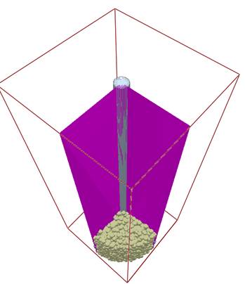
For example, using the settings in the screenshot above any particles exiting the boundary along the Y axis will enter the simulation on the opposite boundary. Linear Periodic Boundaries also allow particles to interact with material on the opposite side of a boundary. In the screenshot below, the particle on the left will be visualized as a whole on the left side of the screen until its center point passes the boundary; however, the particle will still contact material on the other side of the boundary as shown in this graphic.

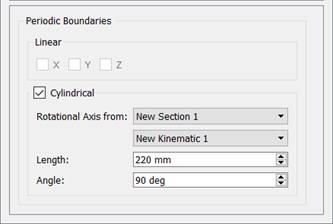
Periodic Boundaries (Cylindrical)
Cylindrical Periodic Boundaries can be set inside a simulation. Unlike the Linear Periodic Boundaries, which act on the Domain Bounding Box, the Cylindrical Boundaries are set by the user and exist inside the domain.

Any particles exiting the boundary plane will enter the opposing plane and all forces, torques, positions and velocities will be rotated by the difference in angle between the two planes. Selecting the  icon allows the boundary to be visualized.
-
A Linear Rotation Kinematic must be set up on the equipment. If the equipment is not rotating the kinematic can have an angular velocity of 0 rad/s.
-
Once a kinematic has been defined select the ‘Cylindrical’ option in the Boundary Conditions and choose a rotation axis from a previously defined kinematic. The vector direction determines the direction and height of the rotational periodic boundary axis.
-
Set the length (radius) of the boundary. The length should extend beyond the walls of any geometry elements involved in the rotational condition.
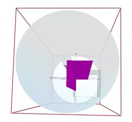
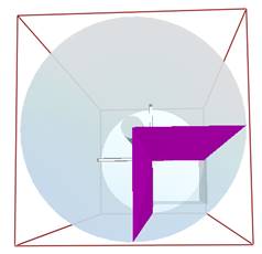
Left: Boundary length of 100 when geometry radius is 200. The above boundary will not be effective as particles can escape beyond the boundary and the walls.
Right: Length of 200 when geometry radius is 200. The above boundary is suitable for the equipment.
-
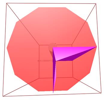
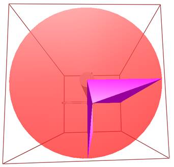
Set the angle of the boundary as appropriate for the simulation. In the image below the mixer has 4 blades at 90 degrees separation. In this case the angle should be 90 degrees.
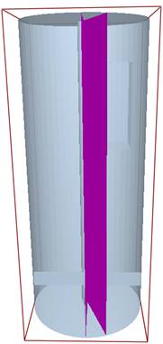
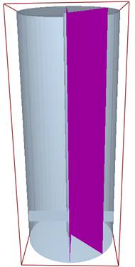
Image above: Boundary showing 20, 45 and 90 degrees.
Cylindrical Periodic Boundary Known Issues and Limitations:
-
A Linear Rotational kinematic is required to setup the boundaries, even if the kinematic has a velocity magnitude of 0.
-
Plugin (API) factories are not supported with Cylindrical Boundary Conditions.
-
Simulator Auto Grid Size is not supported with Cylindrical Boundary Conditions.
-
Coupling Interface is not supported with Cylindrical Boundary Conditions.
-
GPU Solver is not supported with Cylindrical Boundary Conditions.
-
Cylindrical Boundaries are limited to a maximum 150 degree angle.
-
Cylindrical Boundaries cannot be used at the same time as Linear Boundaries.
-
Bonds from the Bonded Particle Model are displayed from particle-center to particle-center across the domain even if particles are in contact through a boundary.
-
Geometry must be rotationally periodic to use the boundary effectively. The two images below show a circle made from 10 edges and one made from 50 edges. If the geometry is not of a high-quality mesh then particles passing through boundaries will catch on non-periodic edges.
Low quality mesh (left), high quality mesh required for boundary condition (right).
-
A central element (cylinder) is required at the mid-point of the boundary. At the center point of the boundary it is possible for a particle to pass through the boundary and contact itself, which can lead to particle explosions. This can be prevented through definition of a geometry section at the center of the boundary.