Getting Started
Introduction to EDEM
With EDEM Creator you can quickly and easily create a representative model of your bulk material. Tools are provided to specify the components of the DEM material model including the contact physics and model particle shape and size distribution. Where required, CAD models of actual particles can be imported and used to approximate model particle shapes and calculate inertial properties. CAD models of equipment geometry can be imported in a variety of formats and model components can be grouped, moved, and copied. The motion of each group can be specified individually. EDEM's Particle Factory technology provides a unique method for efficiently generating assemblies of particles using built-in simple 3D CAD functionality or in association with the imported equipment geometry.
EDEM Simulator is where you configure and control the operation of the EDEM simulation engine which is highly parallelized to run on shared memory parallel multi-core computers as well as on GPU (Graphics Processing Unit). Parallel efficiency increases the larger the model size. Simulation time step and data save intervals can be specified. Simulation status can be visualized and checked in the solve report. EDEM has rewind capability allowing re-run of a simulation from any point with or without changes to the model. EDEM can also be run without the user interface in batch mode.
EDEM Analyst provides a selection of post-processing tools for analysis, visualization and export of simulation data. Bulk behavior metrics can be extracted from the particle-scale simulation data using a range of binning techniques including use of moving CAD volumes synced with equipment geometry movement. EDEM provides fast, parallelized 3D visualizations of the bulk particle system including cutaway views. Visualizations can be exported as stills or video.
EDEM is highly customizable using its Application Programming Interface (API) and Coupling Interface add-ons. User Defined Libraries (UDLs) programmed in C++ using the API enable extension of EDEM’s default physics capability to simulate a very wide range of particle-particle, particle-fluid, particle-structure, or particle-electromagnetic interaction using external models, custom, or third-party solvers. Custom properties allow any property to be associated with particles, contacts, geometry elements and globally within a model.
EDEM User Interface
The high-level EDEM user interface comprises three icons for each of the simulation components: the Creator, the Simulator and the Analyst.
 Creator – Set up and initialize models.
 Simulator – Configure and control the EDEM solver engine.
 Analyst – EDEM data analysis and visualization tool.
You can move between each section by clicking on the toolbar button indicated above.
-
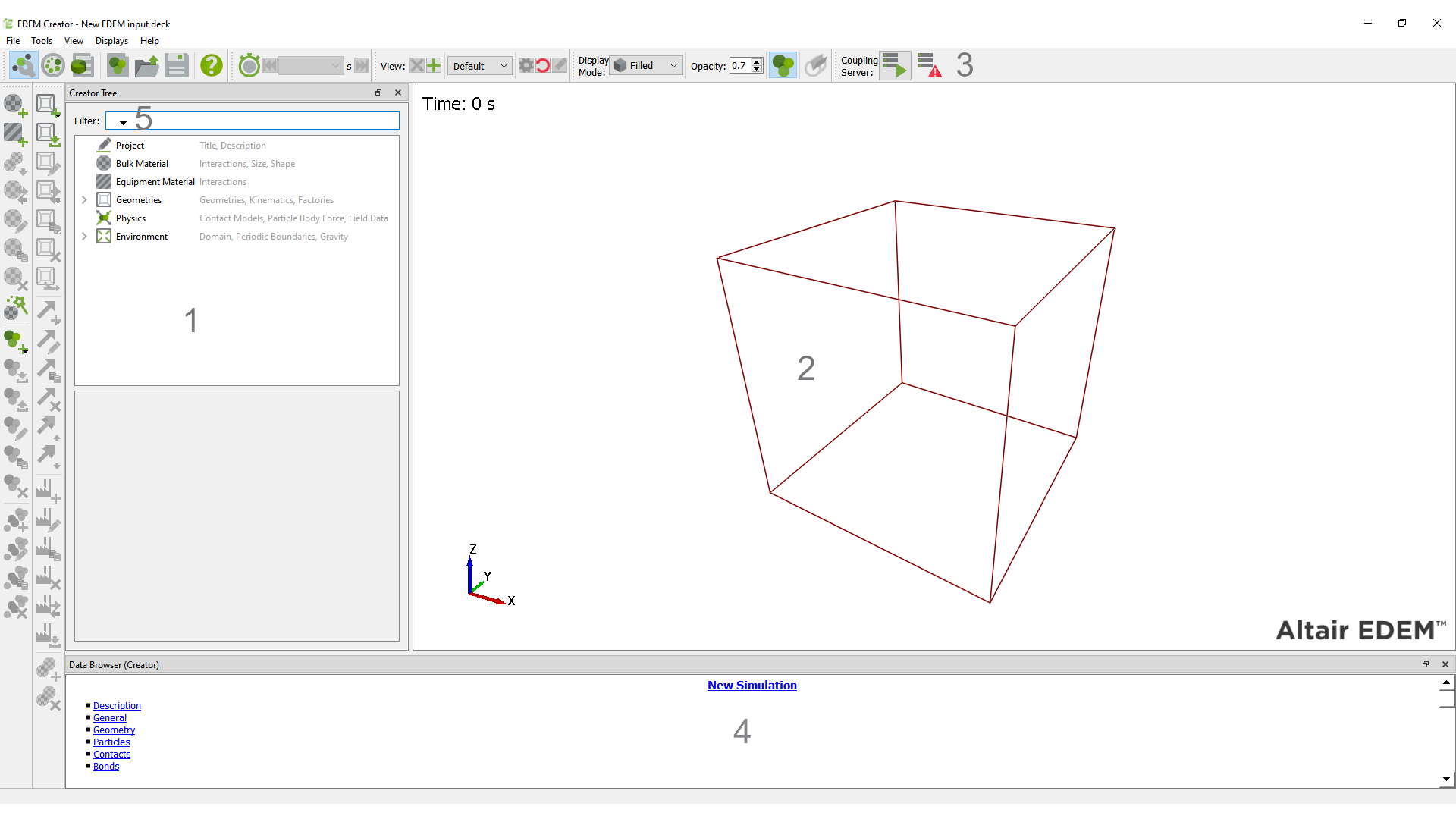
The Creator Tree
The Creator Tree is displayed on the left side of the EDEM window. This allows you to input Bulk Materials, Equipment Materials and set the simulation Environment. The tree is driven by the icons and a ‘right click’ menu system. A similar Tree system is used in the EDEM Analyst.
-
The Viewer
The Viewer displays 3D representations of your particles and geometry. The orientation, position and zoom factor of the Viewer are controlled using the mouse. The arrows in the bottom-left corner of the viewer indicate the current orientation: red (x), green (y) and blue (z).
-
The Icon System
The icons enable the simulation to be setup, some icons are active at the start of a simulation. Others are only active once the simulation is partially setup.
-
The Data Browser
The Data Browser is an .html page that displays detailed information about the contents of the Viewer: For example, particle properties and interactions or the dimensions of a geometry section.
-
The Tree Filter
Filter option allows you to filter items in the tree by typing part of the name of the item. Only items that match, or those that have child items that match, the filter will be shown within the tree. All others are hidden from view.
Filter options 
-
Case Sensitive: When checked this string-based comparisons are case-sensitive, by default this is unchecked.
-
Fixed String: Performs string-based matching.
-
Wildcard: Performs string-based matching with wildcards. ? Matches any single character. * Matches zero or more of any characters
Arranging the User Interface
Floating and Docked Panes
The Creator Tree, Simulator Tabs, Analyst Tree, Icon List and Data Browser can each be floating or docked. By default all panes are docked. To undock a pane double click on its title bar (control area) and place it anywhere in screen. Double click the title bar to re-dock it in its original position or drop it over the left or right edge or the bottom of the screen to dock it in that position.
Opening and Closing Panes
Right-click anywhere on the toolbar. Each of the panes is listed. Select or deselect a pane to open or close it. In addition each pane can be closed using the close button displayed on its title bar.
Camera and Mouse Actions
Use the mouse (with modifier keys) to move the camera around the model in the viewer. You can pan, track, zoom and rotate the camera. Select Tools > Options and then the Mouse Configuration tab to configure these controls.
Pan
Press and hold the left mouse button and drag the pointer to pan the position. The object follows the cursor.
Free Rotate
Press and hold the right mouse button to rotate.
Track
Track lets you move the camera forward and backward while keeping a fixed distance from the target. If the Pan control is described as moving the camera view in the X and Y axes, then the Track would be moving the camera in the Z axis. This can be useful to track objects that may be hidden behind other objects. Usually, when you zoom in to an object the camera stops at the target position. To maintain the same distance between the camera and the target, hold down the shift key then use the left mouse button to track.
Zoom
Use the mouse’s scroll wheel to zoom in and out (or press and hold the middle mouse button and move the mouse back and forth).
Zoom to Box
Alternatively, while holding down the Shift button, press and hold the middle mouse button to draw a box to zoom to.
Rotate on Axis (Screen Axis)
Select Tools > Options > Mouse Configuration and select to rotate on the Screen Axis. The screen’s axes are shown below as dotted lines. With the Shift key held down, press and hold the right mouse button to lock the axis. Move the mouse right to rotate the object around the screen’s right vector.
Rotate on Axis (Model Axis)
Select Tools > Options > Mouse Configuration and select to rotate on the Model Axis. The model’s right axis is shown below as a dotted line. With the Shift key held down, press and hold the right mouse button to lock the axis. Move the mouse up to rotate the object around the model’s axis closest to the up vector.
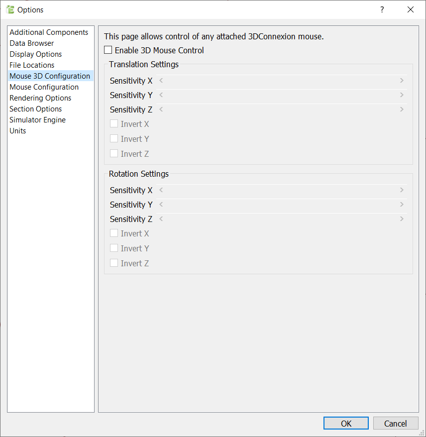
SpaceMouse Devices
EDEM now support the following SpaceBall or SpaceMouse devices from 3Dconnexion: SpaceMouse.
Before running EDEM, be sure that current drivers are installed for your device. EDEM will automatically detect and enable the use of the SpaceMouse once the device is connected and working properly.
The 6 degrees-of-freedom input on the SpaceMouse devices require no special configuration prior to using it within EDEM, however the Mouse 3D Configuration control panel may be used to adjust the sensitivity of the device, as well as how the axes respond to input.
Choosing Units
The units of measurement used throughout EDEM can be configured. By default all quantities are measured in standard S.I. units (Système International d'Unités).
Select Tools > Options > Units to change the units. Changes are propagated throughout the software*. You can set units individually.
| Property | Units Available | S.I. Units |
| Acceleration |
mm/s2, cm/s2, m/s2, in/s2, ft/s2, fpm/s, μm/s² |
m/s2 |
| Angle |
rad, deg |
rad |
| Angular Acceleration |
rad/s2, deg/s2 |
rad/s2 |
| Angular Velocity |
rad/s, deg/s, rpm |
rad/s |
| Charge |
nC, C |
C |
| Density |
g/cm3, kg/m3, lb/in3, lb/ft3, slug/ft3 |
kg/m3 |
| Energy |
J, erg, kwh, btu, ft-lbf, in-lbf |
J |
| Force |
N, dyn, kgf, lbf, ozf, pdl, gf |
N |
| Frequency |
Hz, kHz, mHz |
Hz |
|
Heat Flux |
W, J/S |
W |
|
Length |
mm, cm, m, in, ft, μm |
m |
|
Mass |
mg, g, kg, lb, oz |
kg |
|
Mass Flow Rate |
mg/s, g/s, kg/s, lb/s, oz/s, mg/min, g/min, kg/min, lb/min, oz/min, kg/h, uk ton/h, us ton/h, metric tonne/h |
kg/s |
|
Moment of Inertia |
lb/ft2, kg/m2, g/cm2, lb/in2, slug/ft2 |
kg/m2 |
|
Pressure |
Pa, N/m2, dyn/cm2, kp/cm2, atm, Torr, lb/in2 |
Pa |
|
Shear Modulus |
Pa, ksi |
Pa |
|
Stiffness |
N/m, lb/ft |
N/m |
|
Stress |
Pa, Nm2, lb/in2 |
Pa |
|
Temperature |
K, oC, oF |
K |
|
Time |
s, min |
s |
|
Torque |
Nm, Dyne.cm, gf-cm, kgf-m, lbf-in, lbf-ft |
Nm |
|
Velocity |
mm/s, cm/s, m/s, in/s, ft/s, ft/min, μm/s |
m/s |
|
Volume |
mm3, cm3, m3, in3, ft3, L , μm³ |
m3 |
|
Work Function |
J, eV |
J |
*Graphs are not automatically updated when units are changed. Once units have been changed, click the "Create Graph" button to regenerate graphs.
Windows: Adding EDEM to the file path
The path to the EDEM installation folder must be defined manually. This is done using the environment variables. If EDEM is installed to the default location the EDEM executable (edem.exe) is in the folder:
- C:\Program Files\Altair\2022\EDEM\bin
To add EDEM to the path:
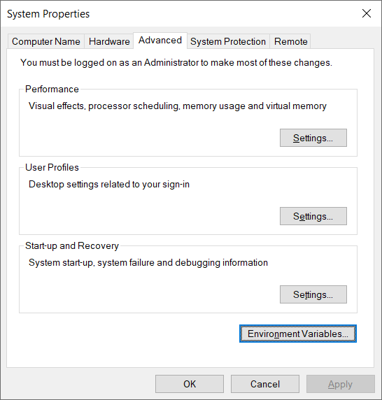
- In the windows control panel navigate to the system option.
- Select the Advanced system Settings
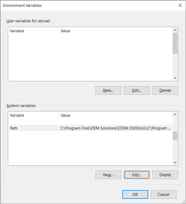
- Select Environment Variables
- In the System Variables panel highlight the Path option then select “Edit”
- Select New
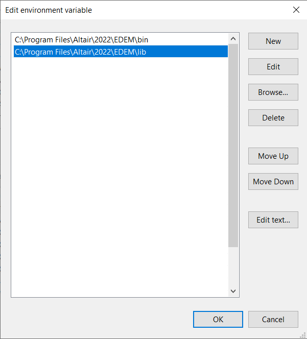
- Type the path to the EDEM install location (default: C:\Program Files\Altair\2022\EDEM\bin\)
- Repeat this for the location of the lib folder (default: C:\Program Files\Altair\2022\EDEM\lib)
- Click ok on each of the windows.