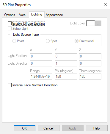
Enable Diffuse Lighting: Lets you create and adjust the direction of the light. This parameter must be activated to apply light source settings.
Note that when creating a 3D surface plot, if you do not activate Enable Diffuse Lighting and have selected a solid color under the Appearances tab, the 3D object will appear flat.
Inverse Face Normal Orientation: Inverts the direction that the light bounces off the surface of the 3D object. Note that Enable Diffuse Lighting must be activated to activate Inverse Face Normal Orientation.
Light Color: Specifies the color of the point, spot, or directional light.
To specify light color for
point, spot, and directional light
1. Activate Enable
Diffuse Lighting.
2. Click Light
Color.
3. In the ensuing Color dialog box, choose a color
for the light.
4. Click OK to close the Color dialog box.
Light Direction: Allows you to specify the direction of the light for Spot light source types. See the Light Source Type parameter for directions on how to specify light direction.
Light Position: Allows you to specify the position of the light for Spot and Point light source types. See the Light Source Type parameter for directions on how to specify light position.
Directional: Directional light has color and direction that you can control, but not position. The light it generates is referred to as parallel light; that is, all directional light travels through an object in the same direction.
To
specify directional light direction using the mouse
1. Activate Enable Diffuse
Lighting.
2. Activate Setup Light.
3. Under
Light Source Type, activate Spot.
4. Click
OK.
In the plot window, a light directional symbol  appears. This symbol represents the light
direction. In the upper left corner of the plot window, the x, y, and z
coordinates of the direction of the light source are displayed.
appears. This symbol represents the light
direction. In the upper left corner of the plot window, the x, y, and z
coordinates of the direction of the light source are displayed.
5. To
control position of the light directional symbol, hold down CTRL+click and drag
the mouse.
As you drag the mouse the light directional symbol moves
accordingly and sheds light on the 3D object appropriately.
Point:
Point light has color and position that you can control; however, it has no
single direction. That is, it gives off light equally in all directions.
To
specify point light position and range through the dialog box
1. Activate Enable Diffuse Light.
2. Under
Light Source Type, activate either Point or Spot.
3.
Enter the Light Position coordinates under X, Y, and
Z.
4. Under Range, enter a value that indicates how far the
light travels.
5. Click OK.
The plot window will reflect
the light position you have specified and light the object
accordingly.
Spot: Spot light has color, position, and direction
that you can control. The light emitted from a spot light has a narrowly focused
inner cone of light as well as an outer cone of light. The light intensity
diminishes as it reaches the outer cone, and there is no light beyond the outer
cone. To control the size of the inner and outer cones, the elements Phi and
Theta are used. The following illustration shows the relationship between these
elements:

To specify spot light position, direction, range Phi, and
Theta through the dialog box
Note: You can only enter
the range, Phi, and Theta values through the dialog box.
1. Activate
Enable Diffuse Light.
2. Under Light Source Type, activate
Spot.
3. Enter Light Position coordinates in the
corresponding X, Y, and Z text boxes.
4. Enter the
Light Direction coordinates in the corresponding X, Y, and
Z text boxes.
5. Enter the range, Phi, and
Theta values in the corresponding text boxes.
6. Click
OK.
The plot window will reflect the light position you have
specified and light the object accordingly.
To specify spot light position and direction using the mouse
1. Activate Enable
Diffuse Lighting.
2. Activate Setup
Light.
3. Under Light Source Type, activate
Point.
4. Click OK.
In the plot window, a
positional/directional symbol  appears, which represents the light source.
In the upper left corner of the plot window, the X, Y, and Z coordinates of the
position and direction of the light source are displayed.
appears, which represents the light source.
In the upper left corner of the plot window, the X, Y, and Z coordinates of the
position and direction of the light source are displayed.
5. To control
the position of the light source, hold down CTRL+right-click and drag the
mouse. As you drag the mouse the symbol moves accordingly and sheds light on
the 3D object appropriately.
6. To control the direction of the light
source, hold down CTRL+click and drag the mouse. As you drag the mouse, the
arrow attached to the  symbol moves accordingly and sheds
light on the 3D object appropriately.
symbol moves accordingly and sheds
light on the 3D object appropriately.
Phi: Allows you to specify the inner cone of a Spot light source. See the Light Source Type parameter for Phi specifications.
Range: Allows you to specify the range of the light for a Spot light source. See the Light Source Type parameter for light range specification directions.
Setup Light: Lets you control the position and direction of the light using the mouse. For more information, see the Light Source Type parameter.
Theta: Allows you to specify the outer cone of a Spot light source. See the Light Source Type parameter for Theta specification directions.