Category: Toolbox > eDrives and Systems > eMotors > Motors
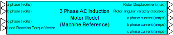
Description: The AC Induction Motor-Machine Reference block is derived from the system of nonlinear differential equations describing electromechanical motion of a three-phase AC induction motor written in the arbitrary reference frame, and reduced to the stationary frame by setting the frame angular velocity equal to 0. Park and Inverse Park transforms are then used to transform three-phase voltage input to DQ voltages and output DQ currents to the three-phase (abc) reference frame. Input requires three-phase voltages, and a load reaction torque vector if external mechanical load is used.
Mechanical dynamics include typical parameters such as, rotor shaft inertia and viscous friction; in addition, nonlinear dissipative factors including, Coulomb friction and stiction models are provided. The AC Induction Motor-Machine Reference block can operate stand-alone to produce output displacement or velocity of the motor alone, or when a Rotational Load block is connected, combined dynamic response. When connected to a Rotational Load block, dynamic parameters are reflected back and combined with the motor dynamics by the linkage ratio. The linkage ratio is specified in the Rotational Load block. This creates proper dynamic motion of the combined motor-load connection. To connect the AC Induction Motor-Machine Reference block to the mechanical Rotational Load block, the rotor displacement and load reaction vector connections from each block must be wired together.
Rotor shaft position, velocity and stator three-phase currents are provided for sensor connections in monitoring and feedback applications.
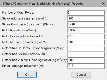
Number of Motor Poles: Indicates the number of motor pole pairs.
Rotor Leakage Inductance: Indicates the specified rotor leakage inductance in henries.
Rotor Moment of Inertia: Indicates the moment of inertia of the rotor with respect to the axis of rotation in kg-m2.
Rotor Resistance: Indicates the rotor winding resistance in ohms.
Rotor Shaft Coulomb Friction Magnitude: Allows specification of constant directional dissipative force (Coulomb model) in units of N-m.

Rotor Shaft Stiction Factor: Allows specification of a stiction force value or break-away torque. This parameter is normally not specified by the motor manufacturer, but can be obtained experimentally. Units are N-m.

Rotor Shaft Viscous Damping Factor: Indicates the factor that linearly relates viscous damping force to angular velocity. This parameter is normally not specified by the motor manufacturer, but can be determined experimentally. Units are kg-m2/s.
Stator Inductance (per phase): Indicates the stator per phase inductance in henries.
Stator Leakage Inductance: Indicates the specified stator leakage inductance in henries.
Stator Resistance (per phase): Indicates the stator per phase resistance in ohms.
Diagram name: ACIM Mach Ref
Location: Examples > eDrives and Systems > eMotors > AC Induction
The following simulation example illustrates the application of the Field Orientated Controller-sim block in controlling speed of a three-phase AC induction motor using a rotary encoder for feedback. Current is sensed using the motor model output currents. The command profile shows stable and accurate control of speed over a wide range of speeds.
