Diagram: Machine Tool
Location: Examples > eMotors > eMotor Tutorials
The typical machine tool lathe is operated from a single-speed motor drive, together with multiple gear selection to vary chuck speed. Here a simpler design is considered: one with a single 10:1 gear reducer and a variable speed control drive for a 3-phase AC induction motor.
The lathe is required to operate with the following specifications:
Maximum work piece load: 1 meter by 0.1 meter diameter aluminum bar stock
Chuck speed control range: 30 to 400 RPM
Speed control accuracy: ± 5 RPM from set point steady state
Maximum load torque: not to exceed 0.3 N-m, introduced by cutting tool
The motor specifications are given as:
|
Motor parameter |
Value |
Units |
|
Stator resistance (per phase) |
9.4 |
Ohms |
|
Stator self inductance (per phase) |
0.402 |
Henries |
|
Stator leakage inductance |
0.032 |
Henries |
|
Rotor resistance |
7.1 |
Ohms |
|
Rotor leakage inductance |
0.032 |
Henries |
|
Number of poles |
2 |
|
|
Rotor inertia |
0.001 |
Kg-m2 |
|
Rotor viscous damping constant |
0.0001 |
Kg-m2 - s |
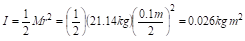
The moment of inertia of the chuck and moving drive assembly is given as 0.1 kg-m2. The moment of inertia of the work piece is calculated as:

Since the axes of the chuck and work piece are coincident, they add to total 0.126 kg m2.
One very effective way of controlling speed by an induction motor is to control the stator field frequency. Since stator flux is inversely proportional to frequency below the base frequency, it is necessary to adjust voltage proportional to frequency to maintain constant flux. For frequency above the base frequency (power supply limitation), the voltage is kept constant. This method is the basis of the design, with one minor improvement. The constant volts to frequency control mentioned above are used as a feed forward leg of a feed forward – proportional integral controller (PI). The PI component of the control is used to adjust any error that may occur due to motor slip and loading from the cutting tool. Motor speed is estimated from motor shaft position measured by an incremental encoder. To drive the motor, an inverter is used with six-step logic to switch polyphase-rectified voltage producing a balanced 3-phase signal.
The first step is to place the following Motion blocks in your diagram:
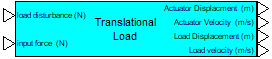
•Rotational Load (under Loads)
•AC Induction Motor (under Machine Reference)
•Rotary Encoder (under Sensors)
Wire the blocks together and use wirePositioner blocks to clearly represent the feedback of the load reaction torque to the motor model.

The rotational load model is used to simulate the lathe chuck and work piece. The rotary encoder model input is connected to the motor’s rotor shaft displacement output connector. The motor displacement output is also connected to the rotational load model. To complete the dynamic interaction between the motor and load, the load reaction torque output connector must be connected to the load reaction torque vector input of the motor model. Note that this wire is thicker than the other wired connections, indicating that it transmits a vector quantity. The vector contains load dynamic parameters that are reflected back to the motor dynamics through the coupling (linkage) mechanism: in this case, a 10:1 gear reduction.
The next step is to enter the parameters for the motor, load and encoder. The parameter values can be changed later to see what affect they may have on the final control solution.
AC Induction Motor block
1. Right-click the AC Induction Motor block to display its Properties dialog box.
2. Enter the motor parameters shown above. These parameter values are taken from the motor specifications table.
Rotational Load block
1. Right-click the Rotational Load block to display its Properties dialog box.
2. Enter the values shown above, and note the following:
•The value for the Load Viscous Damping Factor is a rough guess.
•For the linkage ratio (gear ratio for this application), follow this rule: a factor less than 1.0 multiplies torque, and a factor greater than 1.0 multiplies speed; entering 1.0 produces a direct connection between motor and load.
•Default values are shown for the upper and lower stop limits, but since the Enable Hard Stops checkbox is not activated, hard stop limits are not used in the model. Hard stops are useful in position control system applications.
Rotary Encoder block
1. Right-click the Rotary Encoder block to display its Properties dialog box.
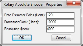
2. Enter the values shown above.
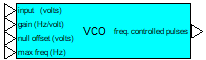
In this step, you use the PID Controller (Digital) block (from the Brush DC category), and the Three Phase Square Wave Inverter (from the AC Induction category) to design the volts/frequency controller for the motor.


After placing the blocks in your diagram, encapsulate them in a compound block using the Edit > Create Compound Block command. Name the compound block Volts/Hz Controller.

This block design requires only 2 inputs and 3 outputs. By default, when you create a compound block, Embed creates and outputs for all the blocks contained in the compound, which may not be appropriate. In this case, you must remove 2 inputs and one output using the Edit > Remove Connector command.
Now label the wire tab connectors by double-clicking each tab connector and entering the names shown below:

Next, right-click the compound block to drill into it. As mentioned before, the process of creating the compound block creates wire connections that may not be needed. Remove all wire connections within the compound by clicking, holding and dragging the wires with the left mouse button to an open space of the desktop and releasing the button.
Within the Volts/Hz Controller compound block, insert the following blocks:
•From Blocks > Arithmetic, add a summingJunction, gain, unitConversion, and / block.
•From Blocks > Signal Producer, add a const block.
•From Blocks > Nonlinear, add a limit block.
Wire the blocks together, as shown below.

The input speed for this block is assumed to be the speed of the chuck; therefore, the gain block is needed to scale this speed up by a gear ratio of 10 since this controller affects the speed on the motor side. RPM is then converted to hertz by using a unitConversion block set to RPMÞrad/sec and then dividing the output by 2p. The value 2p is produced by using a const block set to 2*pi.
The measured speed comes from the Rotary Encoder and is in radians per second. This measurement is converted to hertz simply by dividing by 2*pi. The desired speed in hertz is fed into a summingJunction block, as well as the command input of the PID Controller (Digital) block. The desired speed directly feeds the inverter/amplifier as the feed forward component of the control. PID Controller (Digital) block output is used to correct for minor errors in the feed forward component. The sum of these two components is fed to the inverter/amplifier, the sum is limited to 70 hertz to prevent running the motor into its unstable region of control. The output of the limit block feeds the Three Phase Square Wave Inverter block. The Three Phase Square Wave Inverter block rail voltages must be set to 0 and 1, as shown below, to effectively provide logic control rather than bus level voltages:
The output of the control summingJunction block is scaled inversely proportional to frequency by using a gain block with the factor 230/60. The output is then limited between 0 and 230 volts, and defined to be a variable block with the user-defined name amplifier gain.
To configure the PID compensator, enter the following values into the PID Controller (Digital) block:
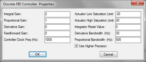
Since the feed forward and derivative gain are set to 0, the block is actually configured to operate as a PI controller. Saturation is set to limit the influence of the integral correction to )20 Hz. Proportional bandwidth is set at Nyquist frequency (½ the sampling frequency); derivative bandwidth does not matter in this controller. The Use Higher Precision parameter is turned ON to allow trapezoidal integration to be used.
Integral reset is not used on this controller, so a const block with a value of 0 is fed into PID Controller (Digital) to prevent integral reset. The actual values for the proportional and integral gain were determined experimentally in the final configuration to obtain minor overshoot and settling in the control.
This completes the construction of the Volts/Hz Controller compound block.
The three outputs for Volts/Hz Controller are connected to the corresponding inputs of the induction motor block. Measured speed from the Rotary Encoder block is connected to the measured speed input of the Volts/Hz Controller block. A slider block, scaled between 30 and 400, is connected to the desired speed input of the Volts/Hz Controller block as RPM speed input. A plot block is wired to compare the desired and actual speeds. The actual speed is determined by converting load angular velocity to RPM. A const block set to 0 is connected to the load disturbance input of the rotational load model. wirePositioner and variable blocks are used to make the diagram legible.
Before simulating the model, click System > System Properties command and make the following selections:
•In the Start Time box, enter 0
•In the Step Size box, enter 0.0001
•In the End Time box, enter 10
Through minor exploration, the motor drive is found to have sufficient torque at all speeds to overcome maximum tool exertion.

Now with a working simulation, you have met the design requirements and can begin optimizing performance. For example, a fairly high-resolution encoder was used for estimating rate. How coarse can the resolution become before performance is degraded? Also, the motor may be oversized for the particular application. Surveys show that over 50% of the motors selected in the US are oversized for their application. Simulation provides a lower-cost alternative to performing extensive analysis or purchasing a variety of motors to empirically determine which is best suited for an application. This is true for any motion control application; not just limited to machine tools.