Category: Toolbox > eDrives and Systems > eMotors > Motors
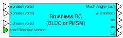
Description: The Brushless DC Motor-BLDC block simulates the motion of a three-phase permanent magnet synchronous motor in machine variables. This block is realized from the system of nonlinear differential equations describing the electromagnetics for a permanent magnetic field and three-phase, Y-connected load together with rotor mechanical dynamics.
Mechanical dynamics include typical parameters, such as rotor shaft inertia and viscous friction. In addition, nonlinear dissipative factors, including Coulomb friction and stiction models are provided. The Brushless DC Motor-BLDC block can operate stand-alone to produce output displacement or velocity of the motor alone, or when a Rotational Load block is connected, combined dynamic response. When connected to the Rotational Load block, dynamic parameters are reflected back and combined with the motor dynamics by the linkage ratio. The linkage ratio is specified in the Rotational Load block. This creates proper dynamic motion of the combined motor-load connection. To connect the Brushless DC Motor-BLDC block to the Rotational Load block, the rotor displacement and load reaction vector connections from each block must be wired together.
Rotor shaft position, velocity and stator three-phase currents are provided for sensor connections in monitoring and feedback applications.
Load Reaction Vector (input): Indicates the vector input used to feedback dynamic parameters and linkage ratio imposed on motor by load model.
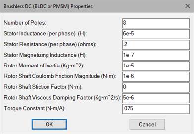
Number of Poles: Indicates the number of rotor poles.
Rotor Moment of Inertia: Indicates the rotor moment of inertia along the axis of rotation in kg-m2.
Stator Resistance (per phase): Indicates the per phase winding resistance of the stator in ohms.
Rotor Shaft Coulomb Friction magnitude: Indicates the constant dissipative force imposed by the rotor bearings/bushings in N.
Rotor Shaft Stiction factor: Indicates the static friction (break-away) force imposed by the rotor bearings/bushings in N.
Rotor Shaft Viscous Damping Factor: Indicates the viscous damping factor imposed by the rotor bearings/bushings in kg-m2/sec.
Stator Inductance (per phase): Indicates the per phase inductance of the stator winding in henries.
Stator Magnetizing Inductance: Indicates the difference between the stator per phase inductance and the stator leakage inductance in henries.
Torque Constant: Indicates the average torque constant of the motor in Newton meters/amp.
Diagram name: Brushless PWM Servo AMP
Location: Examples > eDrives and Systems > eMotors > BLDC
The following example illustrates speed control of a DC brushless motor using a PWM Brushless Servo block in feedback with a rotary tachometer generator. Note that Hall sensors used to commutate the motor are connected through the PWM amplifier.
