Block Category: Real Time
Description: The CAN PEAK read block reads data from the CAN bus.
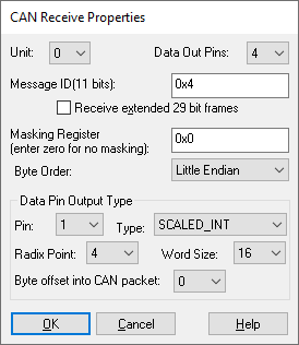
Byte Order: Little Endian is the same as the PC, so no data adjustment is done. Big Endian will cause the 8-byte data packet to be byte swapped.
Data Out Pins: Specifies the number of output connectors on the CAN PEAK Read block. Each connector refers to a data item within the 8-byte CAN packet. Note that the packet length can be from 0 to 8 bytes.
Each data connector corresponds to a data item within the 8-byte data packet of a CAN message. For each connector, you can choose:
Byte Offset into CAN Packet: Selects the byte offset into the 8-byte CAN data packet.
Radix Point: Selects the radix point for Scaled Int data types.
Type: Selects the data type for the connector.
Word Length: Selects word length for Scaled Int data types.
Masking Register: Every bit set in a mask register is a “Don’t care” bit, that means this block will accept any message identifier received that matches bits in the Message ID except those bits set in the Mask. A mask of 0x1FFFFFFF will match all identifiers. A mask of 0 will match only identifiers exactly the same as the Message ID.
Message ID: Specifies the CAN message identifier. This can be from 0 to 0x7FF for 11 bit identifiers, or from 0 to 0x1FFFFFFF for extended 29-bit identifiers.
Receive Extended 29 Bit Frames: The default is 11 bit identifiers. Checking this box will result in the use of 29 bit identifiers.