Category: Toolbox > eDrives and Systems > eMotors > Controllers
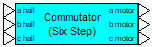
Description: The Commutator-Six Step block provides six step motor commutation logic signals from Hall sensor input.
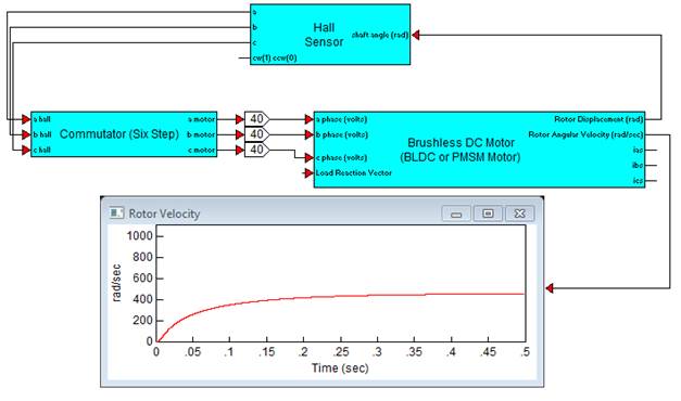
Diagram name: Six Step Commutator
Location: Examples > eDrives and Systems > eMotors > BLDC
In this example, Hall sensors measure shaft displacement. Hall sensor output is fed directly to the Commutator-Six Step block. The output of the Commutator-Six Step block is scaled to the drive voltage and fed to the motor phases. The voltage level can control speed; however, for large transients, current feedback together with PWM improves control performance.