A transition has the following basic format:
trigger(s) [guard] / behavior
Together, the triggers and guards represent a logical expression that evaluates to TRUE or FALSE. When the logical expression is TRUE, the transition is taken to the next state. When it is FALSE, another transition is tested; if there are no other transitions, the state of origin remains active.
For this simple example, there are no triggers or behaviors in the transition specification, only guards.
To define transition specifications
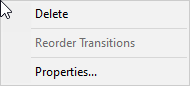
1. Point and right-click over the transition between Init state and Fill state.
The following Pop-Up menu appears:
2. Click Properties.
The Transition Properties dialog box appears.
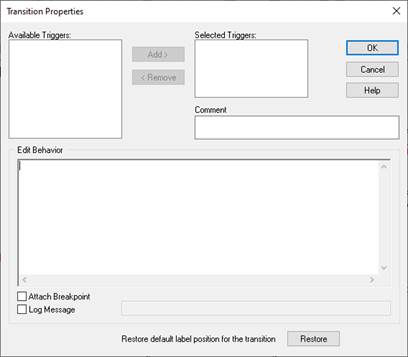
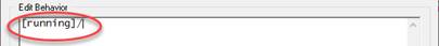
3. Under Edit Behavior, enter the guard using the C language. Enclose the code in square brackets and terminate with a forward slash.
4. Click OK.
5. Repeat these steps to add the following guards to the remaining transitions.
|
Transition |
Guard |
|
Fill to Drain |
[ !running || level > = maxLevel]/ |
|
Drain to Init |
[ !running && level <=0]/ |
|
Drain to Fill |
[ running && level < minLevel]/ |
Your state chart will look like this:
