Category: eMotors > Other Tools > Tools
The Discrete Integrator block provides discrete time integration of signals.
Clock Frequency: Establishes the integrator step time = 1/(clock frequency)
Initial Condition on Reset: Defines the initial value of the integrator output upon reset.
IN: Indicates integrator input.
RST: Indicates Boolean input. When RST is high, integrator output is latched to initial condition; otherwise, integration runs.
LOLIM: Defines the lower limit of the integrator output. Limiting disables further integration in this direction, thus preventing windup.
HILIM: Defines the higher limit of the integrator output. Limiting disables further integration in this direction, thus preventing windup.
Use Higher Precision: When activated, the Discrete Integrator block uses trapezoidal integration; when de-activated, it uses backward rectangular integration.
Diagram name: Discrete Integrator
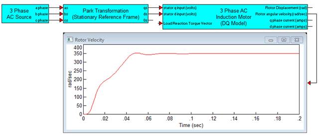
Location: Examples > eMotors > Transforms
The Discrete Integrator block can be used to generate timing pulses. Set IN of the integrator to 1; and set the initial condition to 0. This causes the output of the Discrete Integrator block to ramp with the output value equal to simulation time. Compare this output to the desired interval between timing pulses, and feedback the comparator output to the Discrete Integrator block’s RST. After completing a ramp cycle, the Discrete Integrator block is reset to 0. HILIM and LOLIM are arbitrary; however, they must be within the limits of the timing period.