Entering difference equations
A difference equation is like an ordinary differential equation, but instead of continuous functions, functions in a difference equation take on values only at discrete instances of time. Just as the operator in an ordinary differential equation is the integrator, the operator in the difference equation is the unit delay.
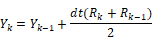
To understand how to represent a difference equation in block diagram form, consider the following example of the trapezoidal integration algorithm in difference equation form:
where:
R = input
Y = output
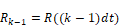
Here, dt is the fixed discrete update time and the subscript k and k-1 denote time in integer multiples of dt. Thus:

and
A DE is converted to a transfer function in terms of the Z operator by replacing occurrences of:

with

Thus:


Performing the replacement and solving for Y/R yields:

Since transfer functions are conventionally expressed in positive powers of z, you must multiply the right-hand side of the equation by z/z to produce:

The procedure to create a block diagram is similar to the one used for continuous time transfer functions; however, the unitDelay block replaces the integrator block. The resulting block diagram becomes:
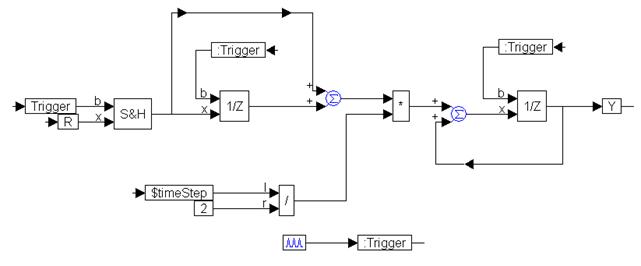
The continuous input signal, R, is made a discrete function by passing it through a sampleHold block to effectively sample and hold its value every time the trigger is activated. The trigger is activated every dt sec using the pulseTrain block, and must be fed into every unitDelay block to synchronize the Embed data flow.