Category: Toolbox > eDrives and Systems > eMotors > Controllers > Field Oriented Controllers
Description: The Field Oriented Controller-sim block attempts to maximize torque output by controlling the stator flux position in the direct (d) axis and current in the orthogonal quadrature (q) axis. The Field Oriented Controller-sim block includes many interconnected subsystems to accomplish this goal. Clarke’s and Park’s transformations are used to convert the three-phase current measurement into DQ frame currents, which are applied to PI direct axis current control and PI quadrature axis current control, respectively. Each of these controllers is commanded by an outer loop PI speed controller that measures rotor shaft velocity, usually from a tachometer or encoder. DQ frame controls are converted back to three-phase using the inverse Park’s transform and space vector pulse width modulation (SVPWM). SVPWM is typically used to lower harmonic content over typical PWM methods and increase DC link voltage. A current model estimates the rotor flux position from measured direct and quadrature currents and known motor parameters. The flux (stator field) position estimate is used in the Park’s forward and inverse transformations.
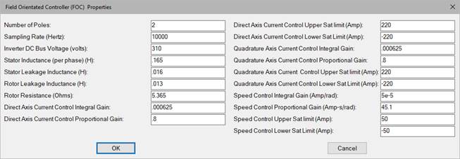
Number of Poles: Indicates the number of motor pole pairs.
Sampling Rate (Hertz): Sets the clock rate for all the operations in the FOC. This rate must be set sufficiently large to provide modulation depth for the SVPWM. A value of 10,000 Hz or greater are typically set. Note that the simulation step size must at least meet this frequency.
Inverter DC Bus Voltage (volts): Sets the voltage level of the PWM pulses for each phase voltage.
Stator Inductance (per phase): Indicates the three-phase AC induction motor stator per phase inductance in henries.
Stator Leakage Inductance: Indicates the three-phase AC induction motor specified stator leakage inductance in henries.
Rotor Leakage Inductance: Indicates the specified three-phase AC induction motor rotor leakage inductance in henries.
Rotor Resistance (Ohms): Indicates the three-phase AC induction motor rotor winding resistance in ohms.
PI Direct Axis Current Controller
PI direct axis current control receives a direct axis current command from a field model and direct axis current measurement. The error between these quantities is then fed to an anti-windup PI compensator.
Direct Axis Current Control Integral Gain: Typically sets the speed (bandwidth) and tracking error of the control loop. Units are 1/sec.
Direct Axis Current Control Proportional Gain: Typically sets the damping of the control loop.
Direct Axis Current Control Upper Sat Limit: Sets the upper output limit of the PI direct axis current controller. Hard limiting is designed to prevent compensator integral wind-up. Units are in amps.
Direct Axis Current Control Lower Sat Limit: Sets the lower output limit of the PI direct axis current controller. Hard limiting is designed to prevent compensator integral wind-up. Units are in amps.
PI Quadrature Axis Current Controller
PI quadrature axis current control receives a quadrature axis current command from the speed controller and quadrature axis current measurement. The error between these quantities is then fed to an anti-windup PI compensator.
Quadrature Axis Current Control Integral Gain: Typically sets the speed (bandwidth) and tracking error of the control loop. Units are 1/sec.
Quadrature Axis Current Control Proportional Gain: Typically sets the damping of the control loop.
Quadrature Axis Current Control Upper Sat Limit: Sets the upper output limit of the PI quadrature axis current controller. Hard limiting is designed to prevent compensator integral wind-up. Units are in amps.
Quadrature Axis Current Control Lower Sat Limit: Sets the lower output limit of the PI quadrature axis current controller. Hard limiting is designed to prevent compensator integral wind-up. Units are in amps.
PI Speed Controller
PI speed control receives a target speed command, and actual speed measurement. The error between these quantities is then fed to an anti-windup PI compensator.
Speed Control Integral Gain: Typically sets the speed (bandwidth) and tracking error of the speed control loop. Units are amp/rad.
Speed Control Proportional Gain: Typically sets the damping of the speed.
Speed Control Upper Sat Limit: Sets the upper output limit of the PI speed controller. Hard limiting is designed to prevent compensator integral wind-up. Units are in amps.
Speed Control Lower Sat Limit: Sets the lower output limit of the PI speed controller. Hard limiting is designed to prevent compensator integral wind-up. Units are in amps.
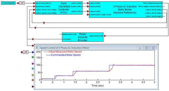
Diagram name: FOC Controller
Location: Examples > eDrives and Systems > eMotors > AC Induction
The following simulation example illustrates the application of the Field Orientated Controller-sim block in controlling speed of a three-phase AC induction motor using a rotary encoder for feedback. Current is sensed using the motor model output currents. The command profile shows stable and accurate control of speed over a wide range of speeds.