Category: Toolbox > eDrives and Systems > eMotors > Sensors
Inputs:
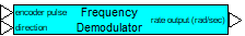
•encoder Pulse: Indicates the input of the demodulator. Acceptable values are 0 and 1.
•direction: Indicates input of the direction of shaft rotation to discriminate between positive and negative velocity. Input is 1 for positive velocity, -1 for negative velocity.
Description: The Frequency Demodulator block demodulates rate signal information from a frequency-modulated signal. Some types of sensors (interrupter type) produce pulses that vary in frequency proportional to the cyclical rate of the sensor. One way to extract the cyclical rate from the carrier frequency is through demodulation.
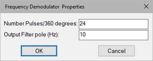
Number of Pulses/ 360 degrees: Indicates the number of pulses that occur over one complete rotation.
Output Filter pole: Defines the roll-off frequency in hertz of the demodulator filter. The choice of the filter pole is usually a trade-off between noise rejection and accuracy of the demodulated rate.
Rate Output: Indicates the demodulated output.
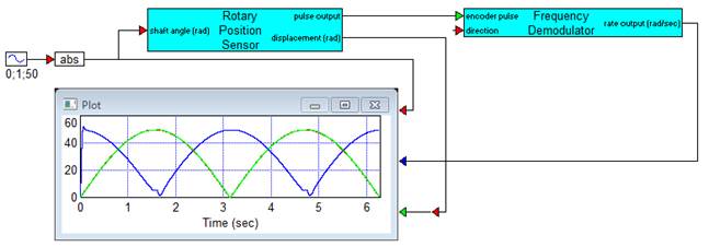
Diagram Name: Frequency Demodulator
Location: Examples > eDrives and Systems > eMotors > Sensors
The following diagram obtains rate measurement from a Hall vane position sensor. The vane sensor produces pulses that are frequency modulated, and so a frequency demodulator is designed to extract the rate signal. Note that direction must be wired out from the Hall sensor block to provide phase sensing for the demodulator.
For this example, the interrupter in the Hall sensing device contained 256 vanes, producing 256 pulses per rotation. A 1 rad/ sec shaft angular velocity is used. At 1 radian second, displacement and rate signals have the same magnitude.