Like the PD compensator, the lead compensator adds phase to a system such that the system reaches the steady state quickly and smoothly. However, unlike the PD compensator, the lead compensator controls the amount of gain added at high frequencies, such that noise is not amplified.
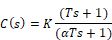
Transfer function
Bode plots
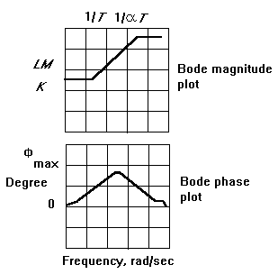
The quantity 1/α is called the lead ratio. It is responsible for the amount of phase added by the lead compensator. The larger the lead ratio, the more spread apart are the pole and zero of the lead compensator, and consequently, the more phase added. The peak phase added lies at a frequency halfway between the pole and zero at:

The characteristics of the Bode plots are summarized in the following lead table:
|
Lead ratio 1/α |
Phase |
|
1 |
0 |
|
2 |
17.5 |
|
5 |
37.5 |
|
10 |
55 |
|
20 |
62.5 |
|
50 |
72.5 |
|
100 |
80 |
To design a lead compensator
1. Based on the Bode plots of the uncompensated system, determine the following:
•The frequency (ω∗) where phase is to be added
•The amount of phase to be added ( )
)
2.
Using the lead table, compute the lead ratio, given the .
Compute the zero:

Compute the lead pole:

Implement the lead compensator and set K slightly less than 1 to counteract the additional gain of the compensator.
3. Adjust the K for the desired transient response.