Category: eMotors > Sensors
The Linear Absolute Encoder block models the quantized displacement measurements obtained from a generic encoding device such as a linear optical encoder or any device that creates incremental counts from linear motion. The block provides the quantized displacement and simulation of processor rate estimation from the quantized signal.
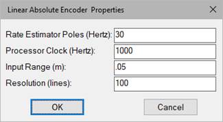
Rate Estimator Poles: Defines the bandwidth of rate estimation. The selection typically requires a tradeoff between rate estimation accuracy and noise. Units are in hertz.
Processor Clock: Defines the processor clock rate for rate estimation.
Input Range: Specifies the end-to-end stroke of the encoder in meters.
Resolution: Indicates the total number of lines over the stroke of the encoder.
Displacement (input): Indicates where the physical displacement is connected. The units are assumed to be meters.
Displacement (output): Indicates where the quantized displacement measurement is read. The units are in meters.
Rate: Indicates where the estimated rate is read. The units are in m/sec.
Diagram name: Linear Encoder
Location: Examples > eMotors > Sensor
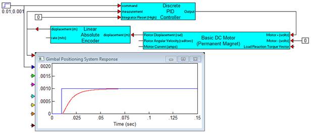
A voice coil actuator is driven by a gimbaled mount for fine angular positioning of a steering mirror. Since the angular stroke is small, a small linear optical encoder is used at the gimbal periphery for estimated angular position and rate feedback measurements. The requirement calls for a step input response rise time of under 10ms with minimal overshoot and settling. Steady state accuracy must be within 2 arc sec. To test initial feasibility for the proposed control, the following simulation diagram is used with the Linear Encoder block to assess a rough design. The number of lines is varied to determine the effects on the dynamic response and steady state accuracy of the feedback loop.