Category: Toolbox > eDrives and Systems > Controllers > PID Control
Inputs:
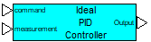
•command: Indicates the input signal to PID controller.
•measurement: Indicates the controlled variable input measurement for PID controller.
Output:
•Output: Indicates the PID controller output signal.
Description: The PID Controller-Ideal block implements an ideal proportional, integral, derivative (PID) compensator for feedback controls with feed forward. This block assumes an ideal linear plant and does not provide for actuator saturation. Furthermore, the compensator provides only a simple derivative and therefore is unable to properly cope with measurement noise.
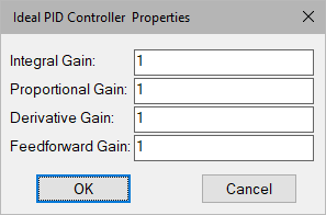
Derivative Gain: Indicates the multiplying factor for the derivative component of control.
Feed forward Gain: Indicates the multiplying factor for the control component that feeds directly from the input to the output of the PID controller.
Integral Gain: Indicates the multiplying factor for the integral component of control.
Proportional Gain: Indicates the multiplying factor for the proportional component of control.
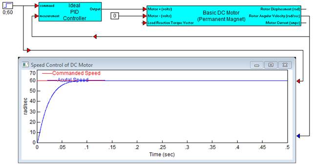
Diagram name: Ideal PID Controller
Location: Examples > eDrives and Systems > eMotors > Brush DC
This example illustrates how easy it is to determine a rough design for the speed control of a DC motor. The PID is configured as a PD compensator by choosing 0 integral and feed forward gains. A basic brush DC motor is used. Proportional and derivative gains are adjusted until adequate response time and overshoot are achieved. You can proceed from this simple feasibility model to include a discrete time controller, and sensor feedback model in simulation, and eventually to hardware in the loop simulation.