Category: Toolbox > eDrives and Systems > eDrives > Inverters
Inputs:
•Duty[1,2,3](0..1): Three-phase duty cycle input. For a three-phase system, this will normally be a three-phase sine wave with an offset of 0.5.
Outputs:
•PWM[1,2,3]: The internally generated three-phase PWM output.
•s: A one-time-step long pulse used to trigger the sampling of an ADC model.
•Ts: The sampling period based on the selected number of events and the switching frequency.
Description: The PWM-3 Phase block is used for <tbs. what?>
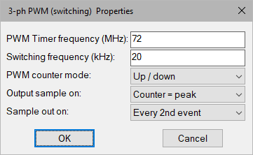
Output Sample On: Sets the moment in the PWM period at which a unit pulse will be generated at the output pin. <tbs. Use initial capitalization with each word>
PWM Timer Frequency (MHz): Specifies the timer frequency used for PWM generation. This will determine the PWM resolution in MHz. <tbs. Use initial capitalization with each word>
PWM Counter Mode: Selects the counter mode of the PWM generation. Note that up/down count mode halves the switching frequency.<tbs. Use initial capitalization with each word>
Sample Out On: Specifies the frequency of the sample pulse.<tbs. Use initial capitalization with each word>
Switching Frequency (kHz): Specifies the required PWM switching frequency in kHz. <tbs. Use initial capitalization for each word>