Category: Toolbox > eDrives and Systems > eMotors > Controllers > PWM Control
Inputs:
•inhibit (0): Provides immediate inhibiting of the output signal and can be used with limit switches for out-of-range control. Active when input is less than 0.3 volts (Active low).
•input (volts): The amplifier input must be a positive voltage. The amplifier saturates beyond the range of 0 to 100% modulation. To avoid operation beyond saturation, the input should be limited between 0 volts and the supply voltage divided by the amplifier gain. Input voltage is limited between 0 and 10,000 volts.
Outputs:
•motor (+): Provides the PWM control signal.
•motor (-): Referenced at a constant 0 volts.
Description: The PWM Brush 2Q block simulates a brush DC motor unipolar PWM amplifier (2 quadrant) that can be used for unidirectional motor control. The control logic simulates a two-device inverter that allows PWM swing from zero to the specified supply voltage over a 0 to 100% modulation range. An inhibit control is provided to disable amplifier output for a control voltage less than 0.3 volts (logic low). Control of the PWM is by direct voltage gain. You specify voltage gain.
To provide adequate simulation of PWM behavior, the simulation step size should be considerably smaller than the inverse of the selected PWM frequency; preferably at least 100 times smaller.
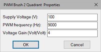
PWM Frequency: Sets the carrier frequency for the PWM in hertz. Note that to provide adequate simulation of PWM behavior, the simulation step size should be considerably smaller than the inverse of the selected PWM frequency; preferably at least 100 times smaller.
Supply Voltage: Sets the voltage level output of the PWM in volts.
Voltage Gain: Sets the voltage gain of the PWM amplifier.
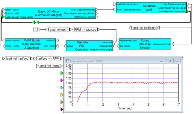
Diagram name: PWM Amplifier 2Q
Location: Examples > eDrives and Systems > eMotors > Brush DC
In this example, a high-speed brush servomotor is used to regulate a very low speed on a high inertia load through a 10:1 gear reducer. Supply voltage for the motor is 8 volts and PWM frequency is 9000 Hz. Voltage gain of the PWM amplifier is set at 20. A PI controller is used to obtain a nearly 0 steady-state error on the speed of the load by using pure integral control at a gain of 100. Load rotation is measured using a 4000-line optical encoder, and rate is estimated using processor filtering. The result shows that the load can be accelerated to the desired rate very rapidly by using the gear reducer. In this example, gear backlash was set to 0. The fine ripple at 1 RPM is due to the noise generated by the encoder and rate estimation.