Category: eMotors > Controllers > PWM Control
The PWM Brush Amplifier 4Q block <tbs. Will Mayank add “Amplifier to block name> simulates a brush DC motor bipolar PWM amplifier (4 quadrant) that can be used for bi-directional motor control. The control logic simulates an H bridge inverter that allows PWM voltage swing between plus and minus the specified supply voltage over a 0 to 100% modulation range. The amplifier is biased at 50% modulation, which represents an average 0 output voltage. This allows bipolar input voltage control. An inhibit control is provided to disable amplifier output for a control voltage less than 0.3 volts (logic low). Control of the PWM is accomplished through voltage gain of the input signal. You can specify voltage gain.
Deadtime that may occur between pairs of switching devices in the H bridge can be simulated by selecting an appropriate deadtime, or set to 0 to disregard this affect.
Motor (+) and Motor (-) output provide the PWM control signal. To connect a single terminal device, the net modulation effect can be simulated by using a summingJunction block to create a difference between the bipolar output ((+) - (-)).
To provide adequate simulation of PWM behavior, the simulation step size should be considerably smaller than the inverse of the selected PWM frequency; preferably at least 100 times smaller.
Supply Voltage: Sets the voltage level output of the PWM in volts.
PWM Frequency: Sets the carrier frequency for the PWM in Hertz. Note that to provide adequate simulation of PWM behavior, the simulation step size should be considerably smaller than the inverse of the selected PWM frequency; preferably at least 100 times smaller.
Voltage Gain: Sets the voltage gain of the PWM amplifier.
Modulation Deadtime: Sets the switching deadtime between H – bridge device pairs. Note that the value of deadtime should be significantly smaller that the PWM frequency, but larger than the specified simulation frequency rate. Units are in seconds.
Input: The amplifier input can be a positive or negative voltage. The amplifier saturates beyond the range of 0 to 100% modulation. To avoid operation beyond saturation, the input should be limited plus or minus the supply voltage divided by the amplifier gain.
Inhibit: Provides immediate inhibiting of the output signal and can be used with limit switches for out-of-range control. Active when input is less than 0.3 volts (Active low).
Diagram name: PWM Brush Amplifier 4Q
Location: Examples > eMotors > DC Brush
This example shows reciprocating motion control of a load through a DC brush motor under PWM control. Rather than using a PID controller, control logic is designed that uses the absolute measurement of load position from an optical encoder. Control signals are flipped each time the motor reaches a determined end position in the positive and negative direction, in this case 1 radian of displacement. The supply voltage to the amplifier was chosen as 100 V with a PWM frequency of 9000 Hz. In this case, a command of plus or minus 10 V is switched through an amplifier gain of 10 so that the PWM is saturated in both directions of motion. A gear 10:1 reducer is used to amplify torque output from the motor.
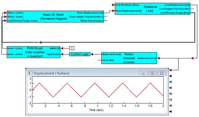
The following diagram details the contents of the Control Logic compound block. Each time the desired endpoints of plus or minus 1 radian is sensed by the encoder, a one-shot fires and switches the flip-flop to reverse motor direction.