Category: eMotors > Controllers > PWM Control
The PWM Brush Motor Amplifier (4Q, Current Feedback) <tbs, will Mayank change the name> block simulates a brush DC motor bipolar PWM amplifier (4 quadrant) with current feedback that can be used for bi-directional motor control. The control logic simulates an H bridge inverter that allows PWM voltage swing between plus and minus the specified supply voltage over a 0 to 100% modulation range. The amplifier is biased at 50% modulation, which represents an average 0 output voltage. This allows bipolar input current control. An inhibit control is provided to disable amplifier output for a control voltage less than 0.3 V (logic low). Control of the PWM is accomplished through current feedback control. Motor current is fed back through a current sense (resistor). The controller for the current loop is PI; the integral and proportional gains can be specified by you. By selecting appropriate values of PI proportional and integral gain, current loop dynamics can be adjusted for any particular motor. Logic is provided that clamps the output to limit load current according to the specified current limit. Anti-windup control is provided in the integrator.
Deadtime that may occur between pairs of switching devices in the H bridge can be simulated by selecting an appropriate deadtime, or it can be set to 0 to disregard this affect.
Motor (+) and Motor (-) output provide the PWM control signal. To connect a single terminal device, the net modulation effect can be simulated by using a summingJunction block to create a difference between the bipolar output ((+) - (-)).
To provide adequate simulation of PWM behavior, the simulation step size should be considerably smaller than the inverse of the selected PWM frequency; preferably at least 100 times smaller.
Direct access to the PWM can be accomplished by setting the current sense gain and current loop integral gain equal to 0, and the current loop proportional gain equal to 1. In this situation, current limiting is still available as long as motor current output is connected to the current sense input.
Supply Voltage: Sets the voltage level output of the PWM in volts.
PWM Frequency: Sets the carrier frequency for the PWM in hertz. Note that to provide adequate simulation of PWM behavior, the simulation step size should be considerably smaller than the inverse of the selected PWM frequency; preferably at least 100 times smaller.
Current Loop Integral Gain: Typically sets the speed and tracking accuracy (bandwidth) of the current control loop. Units are 1/sec.
Current Loop Proportional Gain: Typically sets the damping of the current control loop.
Current Sense Gain: Sets the gain of the current feedback-sensing device. Units are in amps/amp.
Input: The amplifier input can be a positive or negative voltage. The amplifier saturates beyond the range of 0 to 100% modulation. To avoid operation beyond saturation, the input should be limited between plus or minus the supply voltage divided by the amplifier gain.
Current Limit: Sets the maximum average output current the amplifier will provide. Units are in amps.
Inhibit: Provides immediate inhibiting of the output signal and can be used with limit switches for out-of-range control. Active when input is less than 0.3 V (active low).
Diagram name: PWM Brush Amplifier 4Q (Current Feedback)
Location: Examples > eMotors > Brush DC
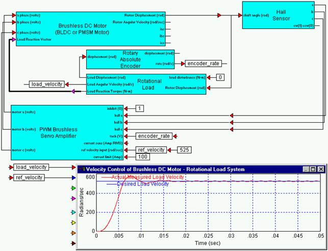
In this example, the 4-quadrant PWM amplifier is used with current feedback and with a cascaded velocity loop to track a reference sinusoidal speed trajectory. The velocity PI controller is set with integral gain at 10, proportional gain at 0.1 and feed forward gain at 0.1. Current loop PI control is set with integral gain at 100, and proportional gain at 1. Current sense is at a gain of 1, and PWM frequency is at 9000 Hz. A 4000-line optical encoder is used to close the velocity loop. The response shows stiff tracking of the reference signal. An interesting result occurs near 0 velocity that may be due to a dropout in the rate estimation from the encoder or possibly not enough modulation depth in the PWM either by design or by inadequate selection of the simulation step rate.