Category: eMotors > Controllers > PWM Control
The PWM Brushless Servo Amplifier block simulates a brushless PWM servo amplifier used to control the velocity of a brushless DC motor. The control logic provides a transformation that decodes Hall sensed motor shaft position and direction to stator field commutation (six-step control). An inhibit control is provided to disable amplifier output for voltage input less than 0.3 V (logic low). All 3-phase voltages are provided with full PWM control (0-100%). A value of 100% represents no modulation. This allows variable speed control. Control of the PWM is accomplished through cascaded loops.
The inner loop is current feedback control. Current sense is fed back through a current sense (resistor) or transconductance gain. The controller for the current loop is PI; you can specify integral and proportional gains. The PI output is clamped between 0 and 100% modulation to prevent control windup.
The outer loop is velocity feedback control. A tachometer input (V) provides the measured shaft velocity that is converted to engineering units (rad/sec) by the tach sensitivity and compared against the reference velocity input (rad/sec). The controller is PI; you can specify integral and proportional gains. The PI output is clamped by the current limit control that limits the current loop reference.

Supply Voltage: Specifies the voltage level for PWM pulses in volts. A positive voltage produces clockwise rotation of the motor. A negative voltage produces counterclockwise rotation.
PWM Frequency: Sets the carrier frequency for the PWM in hertz. Note that the reciprocal of the simulation step size (simulation frequency) must be equal to or greater than the carrier frequency to perform a proper simulation.
Velocity Loop Integral Gain: Indicates the velocity loop PI controller integral gain. This parameter typically sets the steady-state tracking accuracy of the speed control. Units are in amps/rad.
Velocity Loop Proportional Gain: Indicates the velocity loop PI controller proportional gain. This parameter typically sets the speed (bandwidth) of the velocity control. Units are in Amp-sec/rad.
Current Loop Integral Gain: Indicates the current loop PI controller integral gain. This parameter typically sets the steady-state tracking accuracy of the current control. Units are in 1/sec.
Current Loop Proportional Gain: Indicates the current loop PI controller proportional gain. This parameter typically sets the speed (bandwidth) of the current control.
Transconductance Gain: Sets the current to voltage gain of the current controller. Units are in amps/V.
Tachometer sensitivity: Lets you rescale tachometer readings from V to rad/sec. For example, if the known tachometer sensitivity is 200 V/rad/sec, enter this number to scale the reading back to rad/sec.
Diagram name: Brushless PWM Servo AMP <tbs. Will this name change?>
Location: Examples > eMotors > BLDC
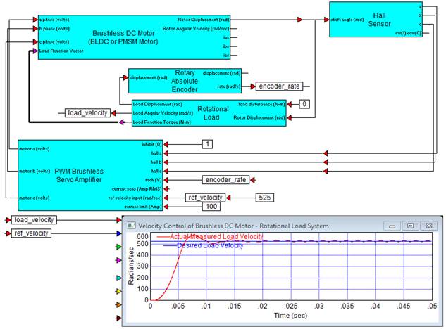
The following example demonstrates the application of PWM Brushless Servo Amplifier block being used to control velocity of a brushless DC motor in feedback with an encoder. Hall sensors are used for commutation of the motor and are connected between the motor shaft and the PWM amplifier. Note that the encoder measures rotor shaft displacement and velocity is estimated for feedback.