Category: Toolbox > eDrives and Systems > eMotors > Controllers > PWM Control
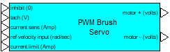
Inputs:
•inhibit: Disables amplifier output for a control voltage less than 0.3 V (logic low).
•tach: Provides the measured shaft velocity.
•current limit: Limits load current according to the specified current limit.
Outputs:
•motor (+): PWM control signal.
•motor (-): PWM control signal.
Description: The PWM Brush Servo-Current and Velocity Feedback block simulates a brush DC motor bipolar PWM servo amplifier (4 quadrant) with current and velocity feedback that can be used for bi-directional motor control. The control logic simulates an H bridge inverter that allows PWM voltage swing between plus and minus the specified supply voltage over a 0 to 100% modulation range. The amplifier is biased at 50% modulation, which represents an average 0 output voltage. This allows bipolar input current control. An inhibit control is provided to disable amplifier output for a control voltage less than 0.3 V (logic low).
Control of the PWM is accomplished through inner loop current feedback control. Motor current is fed back through a current sense (resistor). The controller for the inner cascade current loop is PI, the integral and proportional gains can be specified by you. By selecting appropriate values of PI proportional and integral gain, current loop dynamics can be adjusted for any particular motor. Logic is provided that clamps the output to limit load current according to the specified current limit. Anti-windup control is provided in the integrator.
The outer cascade loop is velocity feedback control. A tachometer input (V) provides the measured shaft velocity that is converted to engineering units (rad/sec) by the tach sensitivity and compared against the reference (rad/sec). The controller is PI, the integral and proportional gains can be specified by you. The PI output is clamped by the current limit control that limits the current loop reference.
Deadtime that may occur between pairs of switching devices in the H bridge can be simulated by selecting an appropriate deadtime, or it can be set to 0 to disregard this affect.
Motor (+) and Motor (-) output provide the PWM control signal. To connect a single terminal device, the net modulation effect can be simulated by using a summingJunction block to create a difference between the bipolar output ((+) - (-)).
To provide adequate simulation of PWM behavior, the simulation step size should be chosen to be considerably smaller than the inverse of the selected PWM frequency; preferably at least 100 times smaller.
Direct access to the PWM can be accomplished by setting both the current and tachometer sense gain and current loop and velocity loop integral gain equal to 0, and the current loop and velocity loop proportional gain equal to 1. In this situation, current limiting is still available as long as motor current output is connected to the current sense input. By selecting appropriate gain combinations in the two PI controls, current feedback only, and velocity feedback control schemes can be configured.
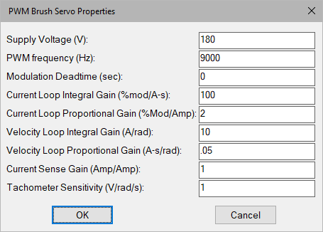
Current Loop Integral Gain: Typically sets the speed and tracking accuracy (bandwidth) of the current control loop. Units are 1/sec.
Current Loop Proportional Gain: Typically sets the damping of the current control loop.
Current Sense Gain: Sets the current sensing device. Units are in amps/amp.
Modulation Deadtime (sec): Sets the switching deadtime between H-bridge device pairs. Note that the value of deadtime should be significantly smaller than the PWM frequency, but larger than the specified simulation frequency rate. Units are in seconds.
PWM Frequency: Sets the carrier frequency for the PWM in hertz. Note that the reciprocal of the simulation step size (simulation frequency) must be equal to or greater than the carrier frequency to perform a proper simulation.
Supply Voltage: Sets the voltage level output of the PWM in volts.
Tachometer sensitivity: Allows you to rescale tachometer readings from volts to rad/sec. For example, if the known tachometer sensitivity is 200 volts/radian/sec, enter this number into the tachometer sensitivity setting of the PWM Brush Servo Amplifier block to scale the reading back to radians/sec.
Velocity Loop Integral Gain: Typically sets the speed and tracking accuracy of the speed control loop. Units are in amps.
Velocity Loop Proportional Gain: Typically sets the damping of the speed control loop. Units are in amp-sec.
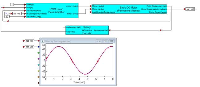
Diagram name: Brush PWM Servo AMP
Location: Examples > eDrives and Systems > eMotors > Brush DC
This example illustrates the single controller package solution for servo tracking control of a DC brush motor with current feedback. A rotary encoder provides the velocity feedback measurement.