
Category: Other Tools > PWM
The PWM (Dual Phase) block provides a 2-phase pulse width modulated signal based on carrier frequency and modulation percent. Modulation is created using the triangular wave – threshold comparator technique. The three inputs are:
Carrier Freq: Indicates the base frequency of modulation carrier in hertz.
Modulation: Indicates the percentage of carrier frequency cycle in which pulse is active (high) from 0 to 100%.
Deadtime: Sets a symmetric deadtime between the A and B PWM phases. Units are in sec.
Diagram name: PWM Dual Phase
Location: Examples > eMotor > Brush DC
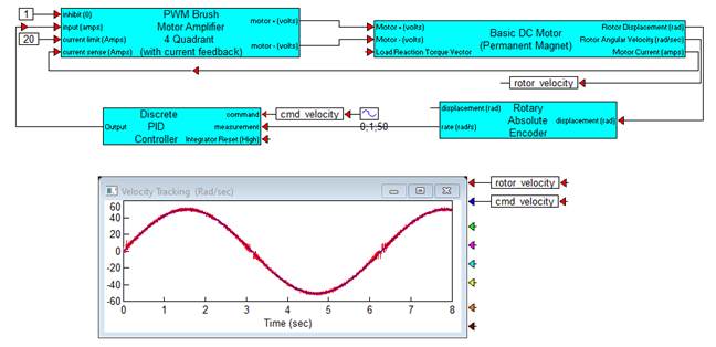
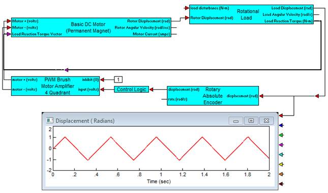
The following example illustrates how the 2-phase PWM can be used to control bi-directional velocity in a closed loop. The two PWM phases are fed to an H bridge power amplifier with voltage rails at ± 28 V. Modulation is biased at 50% from the output of a PI controller limited to ± 50% to prevent windup in the control. An encoder with rate estimation is used for feedback.
