Category: Toolbox > eDrives and Systems > eMotors > Other Tools > PWM
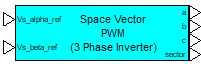
Description: The PWM-Space Vector produces PWM pulses from orthogonal 2-phase input signals using space vector modulation techniques
v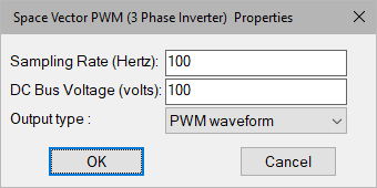
DC Bus Voltage: Defines the output voltage level of the three-phase PWM signals in volts.
Sampling Rate: Defines the processor rate for PWM calculations in hertz. Note that this frequency is typically chosen to be large (8000 Hz or greater). The simulation rate should be at least 10 times the PWM rate to assure proper operation of the simulation.
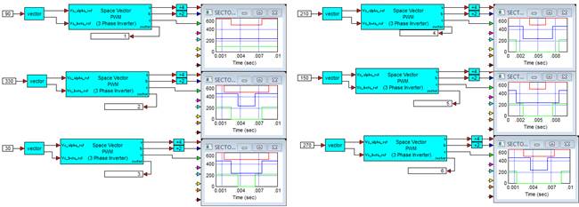
Diagram name: PWM Space Vector
Location: Examples > eDrives and Systems > eMotors > Transforms
Modulation patterns in SVPWM occur based on the location of the timing vector in 6 possible sectors in one complete revolution. The diagram is constructed and duplicated 6 times, changing the input angle in 60 degree increments for each diagram copy that places the timing vector mid-sector for each case. Output phases are then connected to plot blocks to display the patterns for each sector, as shown in the following diagram.