Category: Toolbox > eDrives and Systems > eMotors > Sensors
Input:
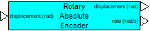
•displacement: Indicates the physical angular displacement connection. Units are in rad.
Outputs:
•displacement: Indicates from where the quantized displacement measurement is read. Units are in rad.
•rate: Indicates from where the estimated rate is read. Units are in rad/sec.
Description: The Rotary Absolute Encoder block models quantized displacement measurements obtained from a generic encoding device such as a rotary optical encoder or similar device. This block provides simulation of processor rate estimation from quantized signal.
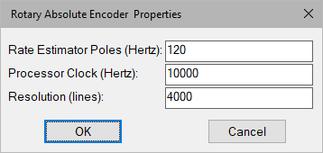
Processor Clock: Defines the processor clock rate for rate estimation.
Rate Estimator Poles: Defines the bandwidth of rate estimation. This parameter typically requires a trade-off between rate estimation accuracy and noise. Units are in hertz.
Resolution: Indicates the total number of lines per revolution.
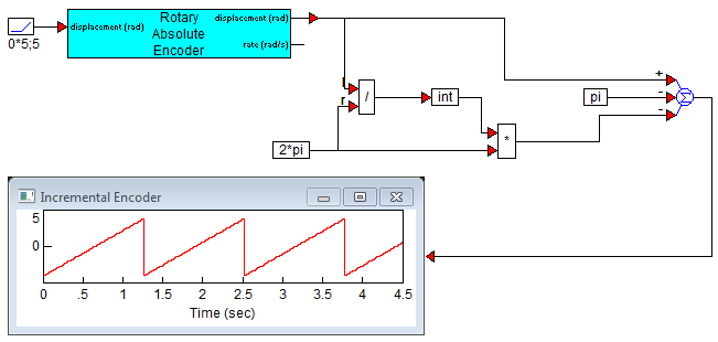
Diagram name: Rotary Absolute Encoder
Location: Examples > eDrives and Systems > eMotors > Sensors
The Rotary Absolute Encoder block simulates an incremental encoder with an assumed built-in counter providing undisturbed unlimited displacement output. A true absolute encoder that uses some type of binary coded scales will reset to 0 position after one complete revolution, and will usually issue an index signal at the 0 position to signal an external counter or processor. In cases where a simulation of an absolute encoder is needed, a simple block construction can be made to calculate absolute angular position using a modulo 2π conversion. The following simulation example illustrates this method. In this example, π is subtracted at the output to provide ±π measurements.