Category: eMotors > Sensors
The Rotary Position Sensor block models the behavior of a vane-operated rotary position sensor that uses digital (ON/OFF) Hall sensors. Shaft angle motion creates pulse output as vane interruption between Hall sensor and magnet complete a flux path and the Hall sensor shuts off (it is normally on). A pulse counter simulates electronics or software that accumulates pulses for displacement measurement. Phasing determines UP/DOWN count. You specify the number of vanes on the wheel and the corresponding window/vane ratio. A cycle is the size of the combined window and vane.
Number of Vanes: Indicates the number of vanes on the interrupter wheel.
Vane/Cycle Size Ratio: Indicates the proportion of space occupied by the vane interrupter vs. total cycle. A cycle is the size of the combined window and vane.
Hall Switching Hysteresis (radians): Sets the Hall device switching hysteresis characteristic. Units are in radians.
Shaft Angle: Specifies the displacement of input device to be measured.
Pulse Output: Indicates the pulse output corresponding to passage of a cycle over a Hall sensor.
Displacement: Indicates the counter output scaled by number of vanes per 1 rotation of the shaft to provide angular displacement in radians.
Diagram name: Rotary Position Sensor
Location: Examples > eMotors > Sensor
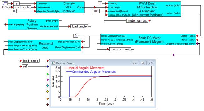
The example below shows a brush DC motor model controlled by a PI compensator in feedback with the Rotary Position Sensor block.