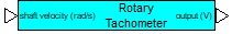
Category: Toolbox > eDrives and Systems > eMotors > Sensors
Description: The Rotary Tachometer block models the behavior of a tachometer generator using the standard ripple model. This block creates output voltage signals proportional to input shaft velocity with ripple frequency components. These components are a nonlinear function of the input shaft angular velocity and number of commutator segments in the tachometer.
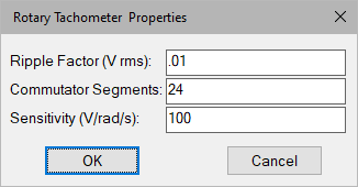
Commutator Segments: Indicates the number of tachometer commutator segments.
Ripple Factor: Indicates the tachometer ripple factor in volts RMS.
Sensitivity: Indicates the tachometer gain in V/rad/sec
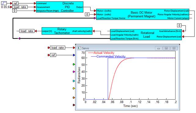
Diagram name: Rotary Tachometer
Location: Examples > eDrives and Systems > eMotors > Sensors
The following example shows velocity feedback control of a permanent magnet DC motor. A load is coupled to the motor by a gear ratio of 0.5, thus multiplying motor torque by a factor of 2. Load velocity is measured by a tachometer with a ripple factor of 0.1 VRMS and 24 commutator segments. The plot zooms in on the velocity as it approaches steady state (60 radians/sec). The ripple can be seen superimposed on the response.