The next step is to enter the parameters for the motor, load and encoder. The parameter values can be changed later to see what affect they may have on the final control solution.
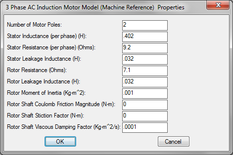
AC Induction Motor block
1. Right-click the AC Induction Motor block.
2. Enter the motor parameters shown above. These parameter values are taken from the motor specifications table.
Rotational Load block
1. Right-click the Rotational Load block.
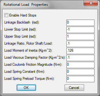
2. Enter the values shown above, and note the following:
•The Load Viscous Damping Factor value is a rough guess.
•For the linkage ratio (gear ratio for this application), follow this rule: a factor less than 1.0 multiplies torque, and a factor greater than 1.0 multiplies speed; entering 1.0 produces a direct connection between motor and load.
•Default values are shown for the Upper Stop Limit and Lower Stop Limit, but since Enable Hard Stops is not activated, hard stop limits are not used in the model. Hard stops are useful in position control system applications.
Rotary Encoder block
1. Right-click the Rotary Encoder block.
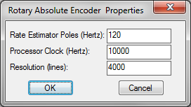
2. Enter the values shown above.